

Offshore engineering surveys for the construction of offshore oil and gas facilities
The present Set of rules establishes General technical requirements and rules, the composition and volume of engineering-geodetic, engineering-geological, engineering-hydrometeorological surveys carried out at appropriate stages (stages) of the development and use of the territory on the continental shelf for construction of offshore oil and gas facilities, including the predesign and design documentation, construction (reconstruction), operation and liquidation (conservation) offshore oil and gas structures.
For engineering surveys on the continental shelf should use terms and definitions in accordance with Appendix A*.
GENERAL PROVISIONS
The composition of oil and gas structures on the continental shelf includes: temporary (mobile offshore drilling units - modu's) and fixed platforms, overpasses, Neftepererabotka facilities and underwater construction of oil, sea vault, infield pipelines, etc. under the continental shelf refers to the zone around the continents extending from the shore line (with a low standing water level at low tide) up to the edge of the continental slope, where there is a sharp increase in the depths of the sea.
Engineering surveys on the continental shelf are characterized by the following features:
-
the specifics of the offshore oil and gas structures and loads on them in the process of operation
-
execution of virtually all types of research with specialized or adapted vessels, floating devices, pontoons or ice
-
the need for extensive use of remote methods of research of geological-lithological profile and bottom
-
the specifics of the Maritime environment, requiring the use of modern and efficient drilling methods, methods of geodetic positioning, surveying and filming in connection with a large distance from the shore
Part of engineering surveys for construction objects on the continental shelf includes:
-
engineering and land surveying
-
engineering-geological surveys
-
engineering and hydrometeorological surveys
-
engineering-ecological surveys.
Engineering research on offshore oil and gas fields are performed to ensure the design and operation of the PBU under the exploratory drilling stages of exploration and development pre-project documentation of field infrastructure, including at the stage of "Justification of investments" and the project documentation (feasibility study (project) and working documentation) for facilities construction.
Engineering surveys for construction of field facilities of the fishery should provide a comprehensive study of natural and technogenic conditions of the shelf and coastal area fisheries, making prediction of the interaction of these objects with the environment, substantiation of their engineering protection and environmental safety.
The program of engineering surveys on the continental shelf drawn up in accordance with customers ' specifications in design stages. The program can be as complex engineering surveys with sections on the types of research and certain types of engineering surveys.
3.10. Survey the products shall be transferred to the client in form of a technical report on the performed engineering survey, prepared in accordance with the requirements of normative documents and state standards on engineering surveys for construction.
5. ENGINEERING AND LAND SURVEYING
5.1. General technical requirements
5.1.1. Geodetic engineering surveys, including engineering-hydrographic works, carried out with the purpose of obtaining geodetic, topographic and hydrographic materials and data needed for the study of natural and technogenic conditions in the construction area of oil and gas structures, justification of design decisions, as well as other types of engineering surveys.
Engineering-geodetic surveys are carried out offshore, on the coast and Islands in the area of the fishery.
5.1.2. Engineering and land surveying must be performed in accordance with the requirements of regulation Hydrographic Service (PGS)-4 (parts 1 and 2), PGS No. 35, PGS No. 37, Instructions for hydrographic survey for drawing up marine plans in scale 1:5000, 1:2000, 1:1000, 1:500 (CALF-71), SNiP 11-02-96, SP 11-104-97, regulations of Roskartografiya in the construction of national geodetic networks to create topographic maps of the shelf and inland waters with the use of global navigation satellite systems.
5.1.3. Engineering-geodetic surveys for construction of offshore facilities includes:
the collection and analysis of available materials, surveying, navigation and hydrographic study of the area (section) of engineering survey;
build (development and recovery) horizontal and vertical geodetic networks on land (the coast and Islands, manmade structures);
create horizontal and vertical geodetic justification to ensure the implementation of the topographic (bathymetric) surveying through the use of global satellite positioning systems (GPS);
engineering-hydrographic works;
topographic (bathymetric) survey;
geodetic support other types of research (including the Stakeout of geophysical profiles, boreholes, points, static sensing, stations, bottom sampling, geophysical binding of engineering-geological workings);
laboratory work including processing of survey materials and preparation of the technical report.
Engineering-hydrographic works include:
organization (if necessary) temporary water level stations;
execution of surveying works (ship, boat, and measurements from ice);
shooting local underwater objects and communications;
survey of surface structures.
5.1.4. Engineering-geodetic surveys are carried out in accordance with the technical specifications of the customer and on the basis of the survey programme.
Program engineering surveys shall conform to the requirements of the Customer's specifications, SNiP 11-02-96 and these regulations.
The survey program must also contain data and information:
justification the details of the shooting of the bottom topography (the depth measurements);
justification of the adopted scale topographic surveys and elevation cross-section of the bottom topography and on land;
description of selected coordinate systems and starting points for satellite geodetic definitions, methods, the vertical and horizontal definitions of the coordinates and geodetic bindings;
the description of the selected technical means (surveying, hydrographic and navigation) and of measures for their preparation for work;
methods of geodetic support of other types of research.
Enclosed to the program overview map should be applied:
the boundaries of the square, which are conducted engineering surveys;
border areas, including accommodation options for exploration and reservoir of hydraulic structures;
the planned location of the reference station GPS or other geodetic points and the location of existing and organized by the hydrometeorological stations and posts of observations of sea level.
In the case of (construction or installation) non-standard support marine geodetic marks to the program must be accompanied by the drawings.
In the process of conducting engineering surveys allowed the adjustment of research programs, in connection with the need for confirmation of results and more information about the objects of study.
In comprehensive survey work program engineering surveys should be linked to other types of research (engineering-geological and engineering-hydrometeorological surveys).
Program engineering surveys should be agreed with the authorities granting permission to engineering surveys.
5.1.5. The results of the engineering-geodetic surveys in accordance with the requirements of the customer's specifications must be drafted in a technical report. Composition of text and graphic parts of the technical report and the annexes to the report shall conform to the requirements of SNiP 11-02-96 and section 8 of these rules.
5.2. The collection and analysis of survey materials and surveys of previous years
5.2.1. The collection and analysis of available materials topographic-geodesic and hydrographic study to be considered:
topographical and hydrographic maps and plans of the shelf and coast, nautical charts;
marine charts and navigation guides;
bathymetric maps made in the process of geological exploration of oil and gas;
cartographic materials of ministries and departments for works on land and water area of the past years;
the coordinates and elevation points triangulation, polygonometry and leveling, including points of satellite geodetic definitions;
the materials of Aero - and space shooting;
hydro-meteorological yearbooks, reference books, tide tables, atlases, tables of amendments, including publication of Roshydromet and other agencies;
5.2.2. The collection of materials and information, if necessary, can be supplemented with reconnaissance surveys of the territory (water area) works.
The results of the analysis of the collected materials and field surveys should be used in the preparation of the engineering survey program for the construction of offshore oil and gas structures.
5.3. Horizontal and vertical geodetic basis. Survey geodesic network
5.3.1. The planned geodesic basis of the engineering-geodetic and engineering-hydrographic works are:
the points of the state geodetic network, including national geodetic satellite network;
the reference points of geodetic networks (geodetic networks thickening), located on land and on fixed AIDS to navigation of the seas;
specially created items of the imaging study (located on the shores and waters).
5.3.2. As initial geodetic framework can be used by the state geodetic satellite network points satellite geodetic network of 1 class (SGS-1). If necessary, can be used items a fundamental astronomic-geodetic network (MEASUREMENTS) and high precision geodetic network (HCV).
5.3.3. The coordinates of the base stations global positioning system (GPS) in the area of work must be determined on points of the State geodetic network, and the items on the world geodetic system WGS-84 - geocentric satellite navigation system. When using the geodetic system WGS-84 used the refined coordinates based on the permanent stations of the global GPS network for geodynamics - tracking stations of the IGS (International GPS Service for Geodynamics).
5.3.4. The coordinates of points of geodetic networks and other points are calculated in the adopted in the Russian Federation the system of rectangular coordinates on the plane projection Gauss-krüger ellipsoid of Krasovsky. Allowed to use other projections and coordinate systems, if this is agreed customers ' specifications and program of works, the expediency of the issuance of accounting materials in a different coordinate system.
5.3.5. Methods of transformation of coordinates of the designated points from one coordinate system to another must be installed in accordance with the requirements of GOST R 51794-2001.
Data on the vertical and horizontal coordinate system and projection used, as well as technical data of recalculation of coordinates from one system to another sets the bodies of the state geodetic supervision, issuing permission to perform engineering surveys in the area.
Satellite receivers and software designed for production work, must be certified for geodetic applications in the Russian Federation and have the certificate of calibration.
5.3.6. Survey geodesic network is created in the development of the state geodetic (including satellite geodetic network) or geodetic networks (geodetic networks thickening). The planned position of the points (dots) of the survey geodesic network should be determined on the basis of the use of satellite geodetic equipment (GPS receivers, etc.) and/or electronic total stations.
5.3.7. As points of geodetic networks thickening and points survey ground can be used for fixed AIDS to navigation of the seas; the points of satellite geodetic definitions, marine geophysical milestones and signs in the form of piles or plain of the pyramids, mounted on the bottom; the centres fixed on any hard grounds on the water (oil rigs, separate rocks, etc.).
5.3.8. Average quadratic error of determination of initial points of survey network in relation to the nearest points of the state (satellite) geodetic network should not exceed:
0.2 m when shooting in the scope of the plan (maps) 1:10000 and smaller.
0.2 mm in the plan scale when shooting in scale 1:5000 and larger.
5.3.9. Altitude based marine engineering-geodetic and engineering-hydrographic works are the points of the state leveling network in the Baltic system of heights 1977:
frames and stamps the state levelling network;
benchmarks level positions, bound to the state levelling network;
the point survey ground, the height of which is determined by the geometric leveling of the III and IV classes.
5.4. Satellite geodetic survey
5.4.1. For navigation and engineering surveys, including when the provision of engineering-geological and other types of research can be used by equipment GLONASS/GPS or differential GPS to determine the coordinates from the satellites.
The equipment used shall be capable of operating at differential static and kinematic modes real time.
Navigation equipment GPS/GLONASS or GPS to provide coordinates outboard instrumentation in specified areas with maximum error not exceeding 1.5 mm at the scale of the reporting tablet.
5.4.2. The software shall provide a driving survey vessel for project geophysical profiles and the output of the vessel at the design point in the graphics mode with given accuracy.
The software shall record the vessel's position (antenna position) at a specified interval (10 MS - speed conversion data positioning system GPS coordinates) in real time and recalculated after the received coordinates in the system WGS-84 coordinate system SK-42 SK-95 in real-time.
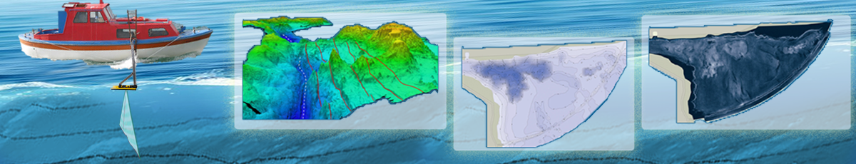
5.5. Sounding works
5.5.1. Implementation of the filming and surveying work for the needs of design and construction of offshore oil and gas structures on the continental shelf must be made in accordance with the following scale number of plans and maps: 1:1000, 1:2000, 1:5000, 1:10000, 1:25000, 1:50000, 1:100000.
5.5.2. Topographic mapping at scales of 1:100000 are performed for the individual areas of undifferentiated topography (with inclination angles up to 2°).
Surveying in sea Straits and bays are typically in scales 1:50000 - 1:2000.
Plans scale 1:1000, 1:2000, 1:5000 and maps of scale 1:10000 are used for:
a detailed study of individual sections of the shelf;
the design and construction of oilfield facilities and utilities.
5.5.3. Detail measurements of the seabed is characterized by the distances between the surveyed profiles (tacks), and at discrete measurements of depths between the points of measurement depending on the nature of the underwater topography and scale.
Max distance between tacks should not exceed 2 cm at the scale of the plan.
5.5.4. The determination of the coordinates of objects on the Islands and manmade structures on the items for the survey ground limit error should not exceed 0.2 m.
When done in moving the profile of the vessel limiting the accuracy of the sentencing project profile in nature should not exceed 10 m and limit the accuracy of determining the coordinates of the object in the water area should not exceed 1.5 mm at the scale of the plan.
Limiting dilution of precision points for engineering-geological investigations (geotechnical boreholes, points, static sensing, etc.) should not exceed 1.5 m.
Error shooting landscape and its image in the plans of coastal land in relation to the nearest point survey ground shall not exceed quantities stipulated in clause 5.11 SNiP 11-02-96.
5.5.5. Average error of determination of the elevations of the bottom, including measurement errors and bring the depths of the Baltic system of heights, must not exceed:
0.2 m to a depth of 5 m;
0.3 m at a depth of from 5 to 30 m;
1% of depth for depths greater than 30 m.
To ensure the required accuracy should be done while surveying the following works:
level of observation;
control measurements in the control of tacks;
calibration of instruments and processing of high-rise studies and water level observations in accordance with the requirements of current regulations.
Control the tacks are laid perpendicular to the survey traverse. For assessment and analysis of random errors to perform a comparison of the depths at the points of intersection of the main and control tacks.
The number of differences of depths at the points of intersection of the main and control tacks close to the limit should not exceed 25 % of the number of control measurements.
5.5.6. Depth soundings are performed, usually in combination with other methods of topographic survey of the water area:
a sonar survey of the seabed soil and underwater objects
aerial photography of shallow water to depths of natural transparency
diving survey;
underwater photography.
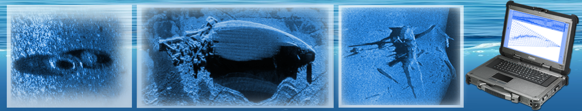
When surveying the seabed (bathymetric surveys) and mapping of different types of bottom grounds, and in identifying and determining the size of the wrecks and is located on the bottom of the underwater communications, the main methods are multipath holotropnoe and location lateral view.
Holotropnoe and multibeam sonar survey method side view made in the form of areal survey in two modes. Initially conducted a scoping site surveys and technical corridors. Next, directly in the proposed hydraulic structures or where detection of submerged objects is detailed examination. The observation network should ensure full coverage midpassage space with some overlap (recommended overlap is 25 - 50 %). Materials of echo-sounding and sonar survey of the seabed are presented in the form of digital or analog recordings, as well as master plans in the coordinate system and the reporting scale maps (plans).
Survey of the coastal strip is generally performed by a system of parallel traverses perpendicular to the shore, or in the presence of complex coastal form at an angle 30 - 45° to the shore. Thus is laid a few check-tacks, of which not less than one for depths up to 5 - 10 m.
Thickening surveying tacks should:
-
on the approaches to ports, anchorages and anchor river estuaries
-
the areas covered by dikes, breakwaters and other hydraulic structures
-
identified in the process of shooting areas with complex bottom topography
The main method of determining the location of the vessel when the survey is a satellite surveying system based on the use of GPS receivers.
Hold shooting out of the tacks in accordance with the planned grid of profiles is carried out using an operational definition of the vessel to make corrections course (operational strip on the tablet working or automatic kurokaze).
The use of other methods, alignments in the directions specified from the shore.
The topography of the seabed should be made, as a rule, hydroacoustic means, providing the required accuracy and the performance of work (surveying echo sounders, multibeam echo sounders, sonars metric, etc.). The use of basting and hand the lot with steel latinam allowed in cases where the use of hydroacoustic means is impossible or inefficient (in the presence of thick algae, in the soundings from the ice, etc.).
The survey should be carried out without gaps in the systematic coverage of the offshore work is scheduled by the system (mesh shooting tacks). For operational control of the production and management of the shooting performed immediately laid tacks on the working tablets or diagrams.
Check sounding is performed, usually, before starting work on shooting tacks and only in case, when shooting is not a system of intersecting zigzag. Check sounding a normal to the crew and not less than 20 cm in the scale of the plan.
Registration data on the depth of the media should be clear, without gaps or interference. All records noise in the echograms should be crossed out and self-explanatory. Allowed the pass to record the ultrasound up to 3 mm, if the analysis of the neighboring depths at the current and adjacent tacks shows that the pass is not associated with distinctive depth.
Causes of intermittent and scattered records on the echograms should be identified in the area of questionable depth should be checked by repeated tacks.
5.5.12. To exclude systematic errors in the measurements of the depth sounder, determination is made amendments in one of two methods:
the calibration of not less than 1 times a day, using tiraumea device on deep horizons 2, 3, 4, 5, 7, 10, 15, 20, 30, 40 and 50 m;
the calculation of private amendments according to the measure of the speed of sound in water or hydrological observations.
When using the method of calculation of private amendments necessary to make daily control comparison of depths to control the correctness of the account of such amendments. Depth for comparisons of measured manual lot with a flat bottom and a depth of 40 m, and in other conditions use tiraumea device. If the difference in depths measured by the echosounder and corrected all amendments and obtained from the control, exceeds double the average of the mean square error (accuracy) measure the depths, the shooting is performed between the control comparisons have to be redone.
5.5.13. The scale of the crew working tablets is prescribed equal to or larger than the scale of a given plan, and the distance between adjacent traverses should be at least 0.5 cm.
When shooting complex topography for operational control of the correctness and sufficiency of the details of the measurements followed the operational manual or automated strip shooting tacks, tablets is posted depths (around the bottom) and interpolated prior (working) isobath (horizontal). The resulting image is used as a preliminary basis for other types of research.
5.5.15. Shooting local underwater objects (base structures, wells, sunken ships and other objects) and communication is performed by methods of sonar, magnetometry and other remote methods, including, where necessary, underwater surveys.
Survey of benthic vegetation, soils and micro-relief are, as a rule, the locator of the lateral review with audit sampling and other methods of decoding the sonar images. This type of work is performed, if for any reason there is no data of engineering-geological survey and engineering-ecological surveys. The results of the survey should be suitable for engineering-geological and engineering-ecological interpretation.
To ensure the necessary accuracy, detail, completeness and reliability of the results of the surveys will be pre-processed imagery. It must be issued working documentation and implemented control and acceptance of field materials in the project area.
5.5.16. Treatment of materials engineering and hydrographic (topographic) surveys are, in General, should include:
checking and evaluating the work undertaken in processing;
material handling definitions places the crew of the ship;
processing of water level observations;
processing of measurement depths;
revision materials sonar surveys, underwater photography and underwater surveys;
the processing of the sample;
processing of topographic and aerial survey;
drafting and editing engineering-hydrographic survey (topographic) maps or plans;
the preparation of the technical report.
Processing of survey materials can be sent to shore base, and, fully or partially, in the presence of automated shooting complexes directly in the project area.
5.5.17. Evaluation of the accuracy of shooting underwater topography is performed according to the differences of the elevations of the bottom of the intersection points of the tacks from which the DNA profiles of one direction accept for the shooting, and perpendicular to them for control. Furthermore, the aggregate survey data computed the expected accuracy of vertical position of isobaths (contour lines) on film original.
Calculations are made according to the PGS-4, part 2, Annex 45.
The accuracy of the measurement of depths shall be considered satisfactory if the following inequality is satisfied
mzсл ≤ mzo,
where mzo permissible error of measurement of the depths, selected according to table. 5.1 percent and translates to meters by the formula:
mzo = mzo %z10-2
z - mean depth;
mzсл - the average quadratic error of measurement depths.
mzсл =
[Δ2] - sum of squares;
n - the number of points of comparisons.
5.5.18. Topographical maps and plans include:
the core crew or cartographic materials;
the preparation of additional cartographic and survey materials;
the compilation of content elements;
reports from adjacent sheets, if any;
the design of the original card;
the proofs of the compilation and design of the original card.
5.5.19. When carrying out engineering-geodetic surveys on the coastal slopes adjacencies should be guided by SNiP 11-02-96 and SP 11-104-97.
The location of the coastlines of the seas must be determined, taking into account local fluctuations in the level:
on the seas with the magnitude of the tide of more than 0.5 m the location is set at the highest level of mean annual observation levels;
on the seas with the magnitude of the tide to 0.5 m at the surf line.
Strip drying on the maps (in the absence of materials of aerial photography the scale required) to be instrumental shooting in all cases, when its width on the plans and maps of scale 1:10000 is more than 5 mm, and on the maps of scales 1:25000 and 1:50000 - 2 mm.
Table 5.1
|
The nature of underwater terrain, ranges of depths, m |
Permissible mean square error of determining the elevations of the bottom when shooting in scale, mz0 in % of the depth. |
||||
|
1:2000 |
1:5000 |
1:10000 |
1:25000 |
1:50000 |
|
|
I. Undifferentiated and sloping with inclination angles up to 2° |
|||||
|
5 - 20 |
1,6 |
1,6 |
1,7 |
2,0 |
2,4 |
|
20 - 50 |
1,0 |
1,1 |
1,2 |
1,4 |
1,6 |
|
50 - 100 |
1,0 |
1,0 |
1,1 |
1,1 |
1,1 |
|
100 - 200 |
0,8 |
0,8 |
0,9 |
0,9 |
1,0 |
|
200 - 500 |
0,7 |
0,7 |
0,7 |
0,8 |
0,8 |
|
II. Divided angles 2 - 6° |
|||||
|
5 - 20 |
1,8 |
2,2 |
2,7 |
2,7 |
Shooting invalid |
|
20 - 50 |
1,1 |
1,3 |
1,5 |
2,0 |
2,0 |
|
50 - 100 |
1,0 |
1,1 |
1,1 |
1,3 |
1,5 |
|
100 - 200 |
0,8 |
0,9 |
0,9 |
1,1 |
1,4 |
|
200 - 500 |
0,7 |
0,8 |
0,8 |
0,9 |
1,0 |
|
Sh Silnoroslye and steep slopes with inclination angles 6 - 20° |
|||||
|
5 - 20 |
2,1 |
2,8 |
2,8 |
Shooting an invalid in the absence of individual technological justification |
|
|
20 - 50 |
1,3 |
1,6 |
2,1 |
||
|
50 - 100 |
1,1 |
1,2 |
1,5 |
1,7 |
- |
|
100 - 200 |
0,9 |
1,1 |
1,4 |
1,7 |
- |
|
200 - 500 |
0,8 |
0,9 |
1,1 |
1,4 |
1,4 |
5.6. Control and monitoring level positions
5.6.1. Water level monitoring should be provided to determine the vertical position of the instantaneous level of the surface (working levels), against which measurements are compared the values of the elevations of the bottom (depths) in the process of the entire work crew of the vessel. In areas where there is no data on the nature of tidal phenomena, in addition to the water level observations during surveying work must be continuous (at least monthly) water level observations to compute a theoretical lower sea level.
On the seas with the tides surveillance level needs to be hourly, and in the moments of highest and lowest values of sea - level increments, as specified in the technical specification.
Water level monitoring should be planned in accordance with the existing area network level of posts, a range of their actions, the nature of the level fluctuations.
When shooting in areas with depths greater than 200 m, beyond coastal level positions, the need (or no need) monitor fluctuations in the level should settle in the work program.
5.6.2. Required quantity level positions in the area of work should be determined by normative instruments of production, hydrographic survey, and regulations of Roskartografiya in such a way that zones of action of adjacent posts had the overlap and any portion was within the range of any level post.
5.6.3. Scope of the sea level gauging are defined so that the maximum difference between the instantaneous levels at any point in the area served by this post, does not exceed:
for coastal water level post - 0.2 m;
for the initial level of the post of the open sea - 0.5 m.
5.6.4. Snap frames and indicating devices level posts is done in the Baltic system of heights, geometric leveling of class IV at the binding distance up to 10 km and leveling of the III class at large distances, in forward and reverse directions.
When performing depth measurements in the coastal zone of the seas limit the error of transfer of zero depths (NTU) from the constant level of temporary posts should not exceed ±5 cm.
5.6.5. Snap frames and indicating devices level posts water leveling is done in calm weather. For areas with tidal survey-otlivami level variations, exceeding the value of 50 cm, the binding elevation levels temporary posts is relations appropriate levels of simultaneous observations for a period of not less than 15 days on them and two permanent or temporary posts.
5.6.6. Transfer to the Baltic system of heights at benchmarks level posts and the point survey ground, located at not available for geometric leveling areas (on Islands, fixed platforms etc.), produced water leveling from two shore positions in accordance with the requirements of normative documents of Roskartografiya and Roshydromet.
Transfer heights for the reference points level posts and the point survey ground can be carried out with the help of satellite geodetic means.
5.6.7. Observations at the level of posts on the seas without tides held at least 4 times a day; during the ebbs and surges of water if the level change 1 hour exceeds 0.1 m, observations are made hourly.
On the seas with the tides on all level positions that do not have level recorders, water level observations are made hourly. When the value of the tide equal to or greater than 1 m observation about moments of total and small waters are produced every 10 minutes for half an hour before and after each low and full of water.
Error in calculating the average sea level should not exceed ±10 cm.
5.6.8. Level the post on the open sea should be set to identify the characteristics of fluctuations in the level remote from the shore area of the shooting and the correct measured depths to the original surface without interpolation in zones with a maximum difference of exceedances of the instantaneous levels at the coast and on the offshore section exceed 0.5 m, and the level measurement is influenced by surge and tidal fluctuations in excess of 1 % of the depth.
5.7. Engineering-geodetic support of other types of research
5.7.1. The scope of works on engineering-geodetic support of engineering-geological, engineering-hydrometeorological and other types of research included:
reconnaissance of the project area;
the development and updating (if necessary) network survey ground;
geodesic support of observations of the sea level (water level monitoring);
high-precision geodetic monitoring of deformations of the earth's surface in areas of development of modern discontinuous tectonic displacements (RTS);
predressed precision of coordinates and creating plans for layout of the project profiles and points of observation and measurement, points of sampling and drilling etc.;
the removal of the project of placing drilling rigs and fixed platforms to the desired spot with the desired precision, driving the vessel on project profiles (the tacks);
geodetic reference points of testing and observations.
5.7.2. The boundaries and size of the area engineering-geodesic and hydrographic works, the scope of the surveys and created plans (profiles and other materials), the degree of information content and positional accuracy of the mounting equipment and devices vessels must be documented in the survey depending on the survey and research.
5.7.3. Reconnaissance of the project area should be conducted to identify, establish or clarify:
preservation of survey markers and triangulation station and poligonometrii in the coastal zone and the possibility of their use;
availability to install GPS base stations;
the need to define additional reference points and ways of getting their coordinates;
places and conditions for the installation of temporary (additional) level of positions;
the presence of places suitable for temporary anchorage and shelter for ships and boats;
the location of the places, convenient for the coastal database survey of parties and approaches to them from the sea.
5.8. Cameral processing of materials of engineering surveys
5.8.1. In the process field engineering surveys should be carried out current processing of materials, which depending on the following services:
mapping geodetic networks;
verification and processing of journals marine measurements (observations);
primary rapid assessment of the quality and preliminary interpretation of the imagery of the sea bottom;
preliminary evaluation of the accuracy of shooting.
5.8.2. Pre-processing of satellite geodetic measurements performed for quality control and conformity assessment to requirements of normative documents and state standards.
The amount excluded from processing at the same time the measurement has been completed, including due to the elevation angle must not exceed 10 % of the total number of observations.
5.8.3. Accuracy assessment of satellite measurements can be performed on the residuals of the closed figures (triangles) for each category of the geodetic network.
5.8.4. As a result of Desk material handling engineering surveys, carried out after completion of the field work should be:
calculation of coordinates of points of the survey network, survey profiles, features rendered on topographic plans and maps, points of geological and geophysical surveys and the drafting of catalogues of openings (pixels);
final processing of materials control measurements and evaluation of accuracy of materials surveys;
interpretation of the survey material;
determination of the accuracy of the performed survey work, planned and high-rise bindings of objects (the calculation of standard errors);
topographical plans and maps of parcels of the continental shelf, bathymetric maps, longitudinal and cross profiles, topographic maps of sites on land;
the consolidated sonar scale plan of shooting;
preparation of the technical report.
5.8.5. Structure of engineering-geodetic and engineering-hydrographic parts of the technical report is provided in section 8.
5.8.6. Primary materials must be stored in the archives of the organization, performing engineering surveys.
5.9. Preparation of maps and plans
5.9.1. In determining the value of the main sections of the relief depending on the character of the bottom relief, depth and scale of the maps should be guided by the table. 5.2.
5.9.2. Design of survey materials on the continental shelf must be carried out in accordance with the requirements of normative documents, regulating the production of hydrographic work in the Russian Federation and normative documents of Roskartografiya and the present set of rules.
Table 5.2
|
The nature of the seabed |
Depth, m |
The contour interval of the contour lines and isobaths on maps and plans, scales, m |
|||||||
|
1:500 |
1:1000 |
1:2000 |
1:5000 |
1:10000 |
1:25000 |
1:50000 |
1:100000 |
||
|
Undifferentiated and sloping with inclination angles less than 2° |
up to 50 |
0,5; 1 |
0,5; 1 |
0,5; 1 |
0,5; 1 |
1 |
1; (2,5) 5 |
2; 5; 10 |
5; 10 |
|
from 50 to 200 |
0,5; 1 |
0,5; 1 |
1; 2 |
1; 2 |
2; (2,5) 5 |
2; (2,5) 5 |
5; 10 |
10; 20 |
|
|
Divided angles 2 - 6° |
up to 200 |
- |
2 |
2; 5 |
2; 5 |
2; (2,5) 5 |
(2,5) 5; 10 |
5; 10; 20 |
10; 20 |
|
Silnoroslye and steep slopes with inclination angles 6 - 20° |
up to 200 |
- |
2 |
2; 5 |
2; 5 |
5; 10 |
5; 10; 20 |
10; 20; 40 |
20; 40 |
Notes
1 the Height of the cross section is shown in brackets, are used on maps of appropriate scale, if the topography of the coastal part of the land has a similar character and/or displayed by contour lines with the same cross section.
2 For best display of landforms and provide a consistent transition to a non-multiple of the contour interval can be additional and minor contour. If necessary, given their digitization.
3, With depths greater than 200 m height of the cross section of the terrain by contour lines should be determined by calculation according to the formula:
h - > cv,
where C is the coefficient, equal to 1.5;
v - error position of the contour lines (isobaths of) height, m;
m - the average quadratic error of determination of the vessel, m;
M - the average quadratic error of measurement of depths, m;
t is the maximum dominant slope of the bottom.
5.9.3. The bottom topography maps of the continental shelf may be displayed by contour lines and spot elevations of the bottom in combination with conventional signs (of the edges and ledges, stones, rocks, reefs, shoals, ridges, flooded valleys, canyons, etc.). The image of the terrain is supplemented by the signatures of contours and characteristic sizes, the relative heights or depths of the individual forms of relief.
Within the selected elementary surfaces of the bottom shall be revealed microforms underwater terrain, sand waves, ridges, shafts, hydromorphone, pits, fields microhollow, pits, "bubbles", etc., which define the characteristics of a relative height.
The average error of the isobaths height must not exceed:
2/3 of the height of the cross section of underwater topography on the seabed with angles of inclination up to 6°;
the height of the section in areas with angles from 6 to 20°.
In areas sinnerschrader and steep slopes of the relief requirements for the accuracy of the depth contours must be justified in the program of engineering studies.
5.9.4. For the design of oil and gas structures used offshore bathymetric maps of sea depth which is given to the long-term level.
5.9.5. The situation in the areas recommended for displaying in conventional signs adopted for nautical charts, as well as with the additional conventional signs.
Contents of maps and plans within the land, Islands, and overwater structures water area are displayed in the symbols accepted for topographical maps of the land.
5.9.6. On topographic maps of the continental shelf are displayed:
strong points of the altitude and the planned geodesic basis, fixed centres, or located on fixed AIDS to navigation of the seas, as well as the permanent water level stations;
a regular hydroacoustic and visual AIDS to navigation of the seas and navigation guidelines (with obligatory attraction of the nautical charts and the official marine navigation AIDS);
the shores and borders of dehydration;
the boundary between the regular wind surges, if the bandwidth of the coast, susceptible, greater than 10 mm at the scale of the plan or map (scale 1:25000 and smaller - 5 mm);
engineering structures and communications;
sea canals, alignment and recommended fairways and paths;
benthic vegetation (phytobenthos) and the vegetation of the coastal zone - according to life forms, as well as typical representatives of stationary and slow-moving benthic animals (zoobenthos);
boundaries and special areas on the water;
the release of oil and gas, the remains of sunken ships, a variety of underwater obstacles.
5.9.7. On cartographic materials should be specified elevation (Baltic system of heights) the set of zero depths of the sea (lowest theoretical level - to the seas with the tides), determined in accordance with the regulations of production, hydrographic survey, and Roskartografiya.
5.9.8. For zero depths on maps of the shelf taken on the seas with tides less than 50 cm average long-term sea level (SMU), the seas with tides of 50 cm and more - the lowest theoretical level (NTU).
5.9.9. To transfer marks of the seabed in water depths beyond the frame of the sheet of topographic maps of the shelf may be an explanatory note on the situation of the long-term average and the lowest theoretical level of the sea against Kronstadt seamark.
5.10. Engineering-geodesic surveys for the development of project documentation (substantiation of investment)
5.10.1. To develop pre-project documentation for construction of oil and gas production facilities is carried out:
the collection and analysis of available materials to navigation-hydrographic and topographic study of the area of research, including locations of coastal points of the state geodetic network, including permanent and periodically the designated points of the state satellite geodetic network (usually GHS-1), thematic maps and other cartographic materials in the area of research.
5.10.2. In case of insufficient completeness and quality of collected materials area of study of research is carried out:
a reconnaissance survey of the area;
the development of the geodetic network and the creation of the survey geodesic network;
topographic (bathymetric) survey in scale, usually 1:50000 - 1:10000 for the selection of designs of platforms and their deployment.
Shooting in scale 1:10000 and, if necessary, and on a larger scale, are performed to study and evaluate the area, explore coastal processes and other phenomena, lithodynamic zoning, engineering-geological survey of appropriate scale, and do other types of engineering surveys.
5.10.3. According to the survey results at the stage of development of justification of investments should be prepared a technical report in accordance with the requirements of section 8 (8.1 "Report on engineering and geodetic researches").
5.11. Survey for development of teo (project) documentation
5.11.1. Engineering and geodetic survey for development of teo (project) of construction of oil and gas offshore facilities includes:
the concentration of the reference points of the geodetic network and survey ground points in the licence area to provide the topographic (bathymetric) surveying a given scale, and the carrying out of the project of arrangement of Providence in nature;
topographic (bathymetric) survey in scales 1:10000 - 1:2000 for the selection of sites of offshore platforms, pumping points of the products, transportation routes of the platforms (the reference blocks) and other objects of fisheries;
the other types of engineering surveys.
5.11.2. For engineering-geodetic surveys at the stage of working documentation are:
the creation of the survey geodesic justification directly on the selected sites of offshore platforms and other objects of fisheries;
topographic (bathymetric) survey in scales 1:2000 - 1:1000 separate area with platforms and other fishing objects located in difficult natural and technogenic conditions.
5.11.3. Technical report on the engineering-geodetic surveys in the stage of feasibility study (project) documentation shall be prepared in accordance with the requirements of section 8 (8.1 "Report on engineering and geodetic researches" of this set of regulations) for completed works.
6. ENGINEERING-GEOLOGICAL SURVEYS
6.1. General technical requirements
6.1.1. Engineering-geological surveys on the continental shelf (on the shelf) are performed to study the engineering geological conditions of the area of construction of offshore oil and gas structures: performance drilling platforms of various types and sites of production to the point of drilling rigs.
Surveys should provide a comprehensive study of engineering-geological conditions of the area and sites the projected construction (and in the confined waters of the shelf the study of engineering-geological conditions of the entire area of oil and gas structures, or the greater part thereof), including relief, geological structure, tectonic, geomorphological, hydrogeological and permafrost conditions, composition, condition, properties and temperature of the soil, the presence of dangerous geological processes and phenomena, with the aim of obtaining the necessary materials to justify the pre-project and project documentation for construction of objects of arrangement of deposits and measures of engineering protection.
6.1.2. When performing surveys in areas of development of geological processes and the distribution of specific soils should take into account the requirements of SP 11-105-97 (parts II and III).
For surveys on the continental shelf of the Arctic seas, where widespread permafrost complex structure (developed on the bottom surface and at different depths) presented stonemantle and cooled below 0° With the rocks (with no ice inclusions) and permafrost, in some places very icy rocks, studies should be performed considering the requirements of SP 11-105-97 (part IV).
6.1.3. When choosing the direction of alignment of the placement of drilling, geophysical observations and field experimental work should take into account that the greatest variability of species on the shelf of the observed normal to the shore, the lowest variability along the coast; as a rule, variability increases with the steepness of the underwater slope and in the confluence of rivers and the development of processes of abrasion.
6.1.4. In the preparation of the forecast of changes engineering geological conditions offshore should be considered extraordinary mobility of sediments in the shallow coastal zone due to development of various lithodynamic processes (sediment load from the outside - the removal of the rivers, Eolian transport, the formation of sediment as a result of abrasion of the coast and erosion of the seabed, transit of sediments along the shore and irreversible care at a depth of abrasion of coarse material under the action of disturbances, accumulation of sediments, detention and accumulation of sediments engineering structures).
The study of lithodynamic processes should be performed in accordance with the requirements of section 7.
6.1.5. On the basis of technical specifications by the contractor, a program of engineering surveys.
In addition to the requirements of SNiP 11-02-96 in the program survey for construction on the continental shelf should contain:
the organization of certain types of works: the scope and sequence, calculation of equipment, tools, equipment, materials, schedule of works;
the equipment of the vessel proteoliposomes equipment, ensure the safety of personnel and technical means in the gas emissions at sea.
To the program of engineering surveys on the continental shelf must make conclusion of the relevant authorities for the protection of the environment, the schedule of performing major works and copies of the approvals of production engineering research.
6.1.6. The detection in the process of detailed engineering-geological surveys for specific sites (due to insufficient prior study of the area of research) conditions that significantly differ from those of programme research (landslides, lenses of silt large power, gas and vodoprovidna jet type, mud cones, the development of submarine permafrost processes, etc.), the contractor must inform the customer about the need for additional work, the compilation of additional technical tasks and make changes in the survey program.
6.1.7. Engineering-geological surveys on the continental shelf should include, as a rule, the whole complex of works, stipulated by clause 6.2 of SNiP 11-02-96under which you must comply with the common technical requirements for their implementation established by section 5 of SP 11-105-97 (part I) taking into account the additional requirements of this section.
This section sets forth additional technical requirements for the execution of certain types of works included in the engineering-geological surveys carried out offshore:
the collection and processing of materials of geological exploration, survey and research of the previous years;
geophysical surveys;
sinking of boreholes with soil sampling and the sampling of bottom soils of the marine bottom samplers;
geotechnical studies of soils;
laboratory studies of soils;
fixed observations;
forecasting of changes in engineering-geological conditions;
cameral processing of materials (including materials and results of researches of previous years) and a technical report.
The detail (scale) of engineering-geological surveys, including volume and methods of work at the appropriate stage (stage) project preparation of the construction of structures on the shelf should be installed in accordance with the requirements of sections 6 and 7 of SP 11-105-97 (part I) subject to the additional requirements of this part of the rulebook.
6.2. The collection and processing of survey materials and surveys of previous years
6.2.1. The collection and processing of survey materials and surveys of previous years it is recommended to perform for each stage (stages) survey taking into account the collection results from a previous step.
The collection and processing could be subject to material containing information about the climate, the nature of the bottom topography and geological history of the region, the stratigraphy, tectonics, the presence of discontinuities, composition, condition, properties, temperature, soil, dangerous geological, geodynamic, geological and cryogenic processes, as well as having the experience of building similar structures, anthropogenic influences and consequences of economic development areas, including:
materials of geological surveying works (in particular, geological maps of the largest scale available for the area), geological engineering (including permafrost) mapping, regional case studies, performance observations;
aerospace imagery data area;
materials of engineering-geological surveys of previous years, made to justify the design and construction of various facilities - technical report engineering-geological surveys, geophysical, seismic, permafrost studies, inpatient observation, and other data, concentrated in government and Agency funds and archives;
results of research works and published materials, which summarizes data on natural and technogenic conditions of the study area.
According to the results of the collection, processing and analysis of survey materials of prior years should assess the level of knowledge of engineering-geological conditions of the study area and evaluation of the possible use of these materials (including term limitations) to address relevant pre-project and project tasks.
6.2.2. The possibility of using the survey materials of prior years should be set, taking into account the limitation period, the changes of bottom topography and geological engineering, hydrogeological and geocryological conditions of technogenic influences.
The Statute of limitations for direct use of survey materials at the stage of project documentation development, it is recommended to take into account changes of the geological environment, but generally it should not exceed: materials and data on physico-mechanical (including permafrost) properties of bottom soils - 5 years in the developed or 10 years in underdeveloped areas; for materials that characterize the geological structure below the layer of moving sediment without any limitations.
This direct use to be, as a rule, the materials of the previous years (geophysical research, description of mine workings, the results of field and laboratory research of soils) which are executed within the boundaries of a site survey, or for a specific customer specifications of corridor trails and the surrounding area. For the width of the adjacent zone is taken 1 - 2 the distance between adjacent tacks holodnogo measurements or continuous seismoacoustic profiling (CSP) at the scale of the engineering-geological survey. With simple engineering geological conditions, the boundaries of adjacent zones can be expanded.
For programming research, technical reports at a stage of predesign research, tracking the dynamics of changes of the geological environment can use data survey made at a greater distance from a more distant time.
6.2.3. On the basis of the collected materials is formulated a working hypothesis about the engineering-geological conditions of the study area and the category of the complexity of these conditions, in accordance with which determine the composition, volume, technique and technology of prospecting works in programming surveys for facility construction.
6.3. Geophysical research
6.3.1. Geophysical studies for engineering-geological investigations on the shelf of the main method are executed, usually consisting of priority activities in all stages (stages) survey for all types of offshore oil and gas structures, in combination with other types of engineering-geological works.
Objectives and problems to be solved by geophysical methods, and guidelines for choosing methods corresponding to the tasks shown in table 6.1.
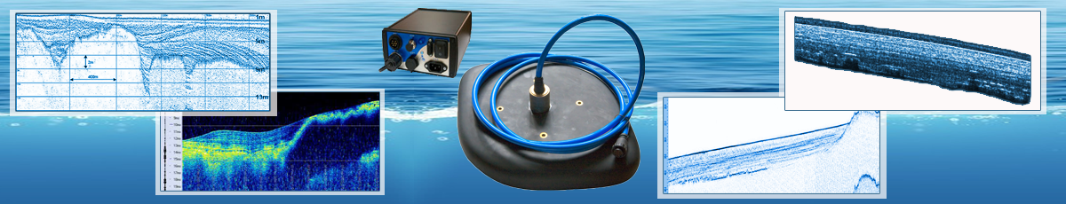
A dominant position among the geophysical methods used in geotechnical investigations is acoustic and seismic methods (continuous seismoacoustic profiling, high frequency seismic, sonar). To search for the bodies of artificial origin used magnetometry. Exploration techniques and radar (GPR) are used sparingly and only for special tasks.
6.3.2. Continuous seismoacoustic profiling (NSP) is used mainly for exploring the upper part of geological section, folded sublimirovanny rocks.
Use single-channel reception (as in the fish finder and locator) and intermediate frequency range (~ 0.1 to 10 kHz). Depending on the required depth and resolution are different technical options of NSP differing in the ways of radiation, energy and technology pull (Annex W).
To bury the sources are used in two ways: near-surface towing and the towing depth.
Near-surface towing use in applications that require large depths at relatively low frequencies or at low water depth. In these cases, the magnitude of penetration is very important and requires careful selection. Near-surface towing due to the need to maintain the desired amount of penetration that puts the ability to perform work dependent on the height of unrest of the sea surface (normally should not exceed half the value of penetration). Working at frequencies exceeding 1 - 1.5 kHz, if near-surface towing is possible, usually, only in calm weather, in closed water areas.
Table 6.1
|
Goal |
Tasks |
Recommended methods |
|
Study of the geological structure and geotechnical conditions of the soil mass in the bottom |
The stratigraphic subdivision of The determination of the depths of the solid rock Mapping of tectonic disturbances The identification of the zones of the curves, permafrost |
Continuous seismoacoustic profiling (CSP) High-frequency seismic |
|
Research for the purposes of seismic hazard assessment |
The study of the nature of the distribution in the plan and in the context of the velocities of propagation of longitudinal and transverse waves |
Seismic exploration with the registration of waves of different types of bottom and benthic plants Seismological methods of NSP Nuclear-geophysical methods |
|
The study of the state of the bottom waters |
Microrelief The outputs of solid rock Man-made traces, traces of ice Akbarali The presence of foreign objects |
The sonar of the lateral review Multibeam holotropnoe Magnetic |
|
Definition of places of discharge of groundwater, gas-saturated zones |
|
The sonar of the lateral review of NSP The method of natural electric field |
|
Detection of activation of corrosion processes |
|
The method of natural electric field |
|
Special |
Mapping of areas that are inaccessible for any reason for NSP |
Radar (GPR) Electromagnetics |
The towing depth should be applied in all cases when it is required to increase the resolution in the upper part of the section, if the depth of the water.
In order that the image does not interfere with the direct reflection from the surface of the water and they generated reverberation, the amount of penetration should be slightly less than half of the water depth. If the water depth is insufficient to fulfill this condition, the possible option of towing close to the bottom. Fluctuations in the depth of the pull should be controlled by the reflection from the water surface and considered in the processing.
6.3.3. High-frequency seismic used for tasks that require reaching depths in excess of achievable single-NSP - to 500 m and more. Used frequency range is between 70 - 150 Hz with a corresponding decrease in requirements for resolution to 5 - 10 m. as the emitter is usually used group of the air; length of the active part of the spit 500 m or more; the number of channels is 48, 96 or more. The system of collection and registration using universal data storage format that allows you to use all the Arsenal of tools of seismic data processing and interpretation. Used the ship must be able pull, control and maintain the depth of towing and maintenance of seismic spit with a length of over 500 m.
6.3.4. The sonar side review is a variant of sonar used for mapping the bottom. The antenna usually is towed behind a boat and scans simultaneously two strips to the left and to the right of the vessel. The bandwidth and resolution should be determined by the technical specifications. The width can vary from 20 to 200 m or more with resolution from a few centimeters to several meters, depending on the specific task and conditions. The network profile needs to ensure full overlap, and the frequency of assumptions should be as attainable for the selected observing system. Commonly used frequency range (80 - 500 kHz) allows to achieve either greater range (low frequency) or high resolution (high frequency). Many devices are designed as dual-frequency (e.g., 100 and 400 kHz).
In the processing of materials used by specialized software tools (real-time or post-processing) carrying out correction of the acoustic images and the compilation of them are the mosaic tablets.
6.3.5. Magnetic survey is used to survey areas of the production structures with a view to the possible discovery at the bottom of the foreign objects. All the requirements for the measurement accuracy should be specified in the technical specification. To avoid the need of setting the variation of station measurements recommended paired device - gradientometer.
6.3.6. Of electrical prospecting methods , it is recommended to use the method of natural electric field (EP) for fixing the corrosion processes and the search of places of discharge of formation water. As the industrial apparatus for using the method of the EP on the shelf is missing, the need for its application when conducting research need to be further specified in the terms of reference and justifies a programme of work.
6.9. Office processing of survey materials
6.9.1. Cameral processing of materials should be performed in accordance with SP 11-105-97 (parts I - IV) and the additional requirements of this section. Given the particular conditions survey (works with floating transience conduct research in connection with their dependence on weather conditions, the difficulty of accurately setting the equipment in place when conducting repeated studies, etc.), a significant amount of office work should have on the current and pre-processing, including in the field (on Board ships and in field laboratories).
6.9.2. The determination of indicators of physico-mechanical properties of soils according to the results of static and dynamic sounding on the continental shelf in accordance with clause 5.8 SP 11-105-97 (part I) must be made on the basis of empirical correlations (tables) between the parameters obtained during the sensing, the characteristics obtained by the direct methods for certain types of soils (Appendix M). In the absence of Appendix M required information allowed to evaluate properties of soils in accordance with Annex And SP 11-105-97 (part I), compiled for the soils developed on the land.
6.9.3. In the preparation of engineering geological maps as source material should be used for engineering-geological and geologic-seismic sections based on the data of drilling, sounding, seismic profiling, high-frequency seismic and other geophysical methods.
On the maps of the investigated areas should reflect:
the sea depth isobaths;
the location and configuration of forms of bottom topography (ridges, hollows, paleovalleys);
the composition and capacity of bottom sediments.
the composition, distribution, ice content, temperature of permafrost and cryogenic structure;
the location, depth and configuration of the gas anomalies.
the presence of dangerous objects of anthropogenic origin;
areas of development of dangerous geological processes (the presence of tectonic disturbances, areas of erosion of the seabed and sediment deposition due to the lithodynamic processes).
6.9.4. In the reporting materials according to seismic profiling, you must enable the structural building, maps of the depths of major reflectors, if necessary - maps of the amplitude and frequency characteristics of the reflected waves, as well as maps of the areas dangerous or unfavorable for the placement of hydraulic structures and communications.
Data engineering-seismometric observations are in accordance with clause 6.8.1.
6.9.5. In the final processing of the materials of engineering-geological surveys, carried out after completion of the field work, performed the compilation and release of the technical report with graphic and text applications in which, depending on the composition of the work performed must be:
location map of geophysical profiles and geological and engineering boreholes, sampling points, points of field research;
engineering geological maps and plans, geological sections, columns, wells, etc., maps, isochrone, the isobaths, the thermal, etc.;
seismic and geological sections, typical profiles;
table of results of laboratory and field studies of soil properties;
the results of the forecast of changes engineering geological conditions.
6.10. Engineering-geological surveys for the development of project documentation (substantiation of investment)
6.10.1. Engineering and geological surveys at all stages (steps) surveys on the continental shelf (including research for the development of project documentation) includes:
drilling engineering-geological boreholes, taking core samples from wells and samples of soil and bottom sediment samples, with the light of technical means and equipment;
geophysical investigations (continuous seismoacoustic profiling, sonar side-scan, etc.);
field and laboratory determination of physical and mechanical soil properties, and granulometric composition of soils and the chemical composition of interstitial waters;
office processing of survey materials, preparation of maps, sections and technical reports.
The amount of work (network profiles with continuous seismoacoustic profiling and egalatarian, the number of drilling wells, sampling of the points of light technical means) are determined and detailed research and reporting scale of cartographic materials that are assigned, depending on the stage (stage) research and installed in accordance with table. 6.8.
6.10.2. During engineering geological surveys on the continental shelf for the development of project documentation in addition to the requirements of SP 11-105-97 (parts I - IV) should provide materials and information to:
General assessment of engineering-geological conditions of sites of MODU and fixed platforms;
choice of alternative options, the most favorable for the placing of hydraulic structures;
justification preliminary calculation of fixed platforms;
obtaining data required for production to the point of exploratory drilling, floating drilling rigs;
the definition of the category design complexity of bottom grounds specified in the technical specification mechanisms;
justification of the composition and quantities for geotechnical investigations at later design stages offshore oil and gas hydrotechnical facilities;
creation of high-quality forecast of changes engineering geological conditions in the construction and operation of offshore oil and gas hydrotechnical facilities.
Table 6.8
|
Types of work |
Detail survey and reporting the scale of cartographic materials |
||||||
|
1:200000 |
1:100000 |
1:50000 |
1:25000 |
1:10000 |
1:5000 |
1:2000 |
|
|
Continuous seismoacoustic profiling when using high-frequency seismic and holothuroidea network, km |
10,0 - 2,0 |
5,0 - 1,0 |
1,0 - 0,25 |
0,5 - 0,125 |
0,2 - 0,05 |
0,1 - 0,025 |
0,05 - 0,02 |
|
GLBA, magnetometry, the distance between the longitudinal profiles, km |
- |
- |
- |
- |
0,15 - 0,05 |
0,1 - 0,025 |
0,05 - 0,01 |
|
The total number of observation points per 1 km2 (wells, points of sensing, geophysical stations and pickets) |
0,5 - 1,1 |
1,0 - 2,2 |
2 - 5 |
6 - 12 |
20 - 40 |
40 - 100 |
200 - 500 |
|
Including - the minimum number of points sampling using marine sampling equipment, geotechnical drilling and soil tests in the array |
0,15 - 0,35 |
0,35 - 0,7 |
0,5 - 2,0 |
2,0 - 4,0 |
6 - 16 |
15 - 30 |
50 - 150 |
Notes
1 Network profile can thicken or discharged in some places of the area of the shooting 1.5 - 2.0 times, depending on the specific engineering geological conditions and the type of planned facilities.
2 When selecting the amount of field work (a network of profiles or the number of observation points) should be guided by the principle of "big detail in a higher category of complexity of engineering-geological conditions".
3 In the assessment of category of complexity of engineering-geological conditions should be guided by the app E.
6.10.3. Engineering-geological surveys on the continental shelf for developing pre-project documentation should be detailed (to scale), which is determined on the basis of the survey, taking into account the area of the shooting, degree, area of study, category of complexity of engineering-geological conditions (Appendix E).
For study of engineering-geological conditions of the area oil and gas structure, or part thereof, and to study the engineering-geological conditions of the area proposed placement of oilfield facilities and utilities engineering-geological surveys should be done at the scale of 1:25,000, 1:50,000, and (in the presence of justification) 1:100000, 1:200000.
On the site of the PBU engineering-geological survey is performed in the scale 1:5000 - 1:10000 at the site of 55 km (for Jur - 33 km).
If the position of the structures tentatively identified, engineering-geological surveys should be done at the scales 1:10000 - 1:25000 square at least 11 km to identify preodolen should lay two geophysical profile with a length of 2 - 3 km (through the center of the site, perpendicular and parallel to the shore).
When the decisive influence of engineering-geological (including the Arctic shelf permafrost) conditions for the adoption of design solutions is permitted by agreement with the customer to perform geotechnical investigations commensurate with the development stage of the project.
6.10.4. The boundaries of the engineering-geological survey and criteria for selection of the site of the proposed construction specified in the technical assignment for engineering surveys and specified when compiling the program, based on the need to obtain a General assessment of engineering-geological conditions of oil and gas area of the structure, district (area) proposed construction of offshore oil and gas hydrotechnical facilities.
When you assign borders shooting should take into account the need to identify the whole complex of natural factors influencing the formation and development of engineering-geological processes within the study area.
6.10.5. Engineering-geological surveys on the continental shelf for developing pre-project documentation should be provided with a minimum range of works including:
the collection and processing of survey materials of prior years, including the decoding of Aero - and cosmometrical;
geophysical investigations (continuous seismoacoustic profiling - NSP; the sonar side-scan - sonar; high-frequency seismic survey);
preprocessing of geophysical data, and coordination with the customer transfer point the construction of the detection conditions, complicating the construction or operation of facilities;
drilling engineering-geological boreholes, taking core samples from wells and samples of soil and bottom sediment samples with light and heavy technical equipment (LTS and TTS);
field and laboratory determination of physical and mechanical soil properties, and granulometric composition of soils and the chemical composition of interstitial waters;
processing of materials surveys, preparation of maps, sections and technical reports.
6.10.6. The distance between the profiles (tacks) continuous seismoacoustic profiling and echo-sounding, high-frequency seismic and magnetic surveys, as well as the number of observation points (including boreholes and sampling points using the sea samplers) are installed in accordance with table. 6.8.
The depth of geophysical research determined the geological structure of the study area and objectives of the survey and depend on the source of seismic vibration excitation and the predominant frequency of the excited oscillations and installed subject to the requirements of subsection 6.3.
If the soil be acoustically impervious, the number of engineering-geological workings should be increased; the number of wells and the distance between them is justified in the programme of works.
6.10.7. Drilling should be carried out in accordance with the requirements of subsection 6.4 in points selected according to previous geophysical investigations (to avoid places that are unfit to host the site).
Engineering-geological wells should be placed based on the need of sinking all stratigraphic and genetic complexes of the studied area within the specified depth, given the location of the geomorphologic elements of the relief mikroform and cryogenic structure of permafrost (Arctic shelf).
When performing surveys on-site with a large thickness of loose Sands, Rakosi, peat, silts, fluid and temacapulin of clayey soil (much higher than the expected value of the compressible strata of the soil Foundation) by 30 % of drilling wells should be held to their full capacity or to a depth where they do not affect the stability of structures. The depth of the other mines are encouraged to nominate in accordance with the table. 6.9.
Within the contours of the future facilities, if known, its design and size, you should take at least two wells, as a rule, with the penetration of the entire thickness of loose soils, but not less than the area of structure interaction with the geological environment. When one of the wells used for sampling and the other for static sensing.
If necessary, the sinking of boreholes may be increased to the depth required for data interpretation of acoustic and seismic profiling.
6.10.8. Definition of indicators of soil properties field and laboratory methods should be performed in accordance with the requirements of the PP. 6.12, 6.15 SP 11-105-97 (part I) and subsections 6.5 and 6.6.
Determination of the natural moisture of the soil sample is recommended immediately after his ascent to Board the vessel. The determination of other soil characteristics is produced depending on the technical possibilities on Board the ship or in stationary ground laboratories. It is necessary to comply with the requirements for the selection, transport and storage of samples in accordance with GOST 12071-2000.
6.10.9. Seismic hazard assessment of the area of work, usually done on the basis of collection and generalization of literary and Fund materials research of the past years, regional engineering-geological researches of General seismic zoning (GSZ) and detailed seismic regionalization (DSR).
When conducting surveys for pre-project documentation for additional technical specifications and with appropriate justification, it is recommended to create a temporary network of seismological stations located on land in the coastal zone, and to organize the registration of earthquakes through automated bottom seismic stations from the extension program.
6.10.10. Technical report on engineering-geological conditions of the study area shall be prepared in accordance with the requirements of SP 11-105-97 (paragraph 6.17 of part I, paragraph 6.18 of part IV) and section 8.
Table 6.9
|
Construction type |
Sea depth, m |
Depth geotechnical drilling, m |
|
|
Clay soils from flowing to jugoplastika consistency, friable Sands |
Clay soils solid and semi-solid consistency, dense Sands and medium density, permafrost |
||
|
Fixed platform with pile Foundation* |
More than 150 From 60 to 150 Less than 60 |
In coordination with the design organization |
|
|
90 - 120 60 - 80 |
50 - 80 40 - 50 |
||
|
Fixed platform gravity |
Up to 50 |
At least 0.7 - 1.0 width (diameter) of the platform |
Not less than 0,5 - 0,7 of the width (diameter) of the platform |
|
Bulk (reclaimed) Islands (dyke) |
Two heights dumping (reclamation) |
Half the height of dumping (reclamation) |
|
|
Jur |
Up to 50 |
25 - 30 |
15 - 20 |
|
The marine trestle |
Up to 60 |
40 - 50 |
25 - 30 |
Note - Take the depth of the wells should be at least 15 % larger than the expected depth of piles.
In some cases, by agreement with the customer in the target areas is allowed technical reports to be engineering-geological conclusion, including the following sections: introduction, geological structure (if necessary), engineering-geological conditions with the characteristics of physical and mechanical properties of soils, conclusions and recommendations. To conclude, we need to make engineering geological maps, cross sections, tables of soil characteristics, the results of laboratory study and statistical processing.
The primary materials to be deposited in the archives of the organization, performing engineering surveys include:
logs of drilling operations;
journals of field experimental work;
statements, and logs of laboratory tests;
materials testing, inspection and determination of adjustments of equipment and instruments;
field descriptions of sampling stations;
field logs and data of geotechnical investigations (CPT, DRT, etc.);
primary materials (digital, analog) geophysical surveys.
6.11. Geological engineering survey for development of teo (project), working documentation
6.11.1. Jackup drilling installations (Jack-up). Engineering-geological surveys for the production of Jack-up rig performed to obtain data on seabed topography and soil conditions for calculations of the depth of the indentation of the supports of the Jack-up in the soil, ensuring its safety during drilling and well testing, as well as its elimination and the removal of the installation from the point of drilling.
Allowed with appropriate justification, to be included in the survey perform certain types of survey works of the volume of the subsequent surveys for the planned future construction at this site of fixed platforms.
6.11.2. Engineering-geological surveys for the production of Jack-up rig for a drilling site must be performed in one step (stage) in accordance with the requirements of table. 6.8 and 6.9. At the same time, given the knowledge of engineering-geological conditions of the area oil and gas structure, engineering-geological surveys should be done on the ground, typically at least 11 km in the scale 1:5000 (allowed 1:2000 in difficult engineering-geological conditions and 1:10000 in simple terms).
In shallow waters or when insufficient knowledge of bottom topography bathymetry is required in addition (if not the most favorable corridor approach to determine the position and removal of Jack-up rig from the drilling site), therefore a plot of bathymetric shooting is possible at 33 km for maneuvering the Jack-up rig.
6.11.3. The implementation methodology of engineering-geological surveys for the production of Jack-up rig to the drilling location, the quantity and composition of works mainly meet the requirements of subsection 6.10.
When performing laboratory testing by triaxial compression is allowed not to perform tests consolidated drained the scheme, given the length of stay on the point.
6.11.4. Stationary structures. Geotechnical investigation for project development (working draft), working documents in the area of survey is determined by the size of fixed structures, auxiliary structures (e.g. anchor system) and can be 0.1 - 1 km2 or more.
Engineering-geological surveys for development of design documentation for construction of fixed structures (gravity platforms, pile platforms, gravity-pile platform, the platform on suspended supports, the support base for wells with underwater completion) is performed in accordance with the common for this stage of the research rules. Technological features surveys for these structures are associated mainly with differences in the depth of drilling engineering-geological boreholes (tab. 6.9).
Engineering-geological surveys on the continental shelf in the area from 0.01 ha to 1 km2 for the development of the project of permanent construction of hydraulic structures are performed with level of detail (scale) 1:2000 - 1:5000 with the purpose of complex study and evaluation of geotechnical (including permafrost for the Arctic shelf) conditions in the zone of interaction of structures with geological environment and prediction of their changes in the process of construction and operation of buildings.
6.11.5. The composition and method of engineering-geological surveys on the continental shelf depends on the type of the designed structures (platform gravity type platform on a pile Foundation, etc.).
At the sites of production platforms gravity should be received data necessary for calculations:
the precipitate and consolidation of the Foundation soil;
resistance to the introduction of a "skirt" (if necessary);
local contact stresses (if necessary);
activities for preparing the site for production platforms (alignment, strengthening of soils);
dynamic stability of soils under ice, wave, and seismic loads.
At the sites of production platforms, the pile type should be obtained the data needed to determine:
the calculated resistance of the soil to the bottom of pile Foundation;
the type and size of piles;
the allowable load on the pile.
6.11.6. The boundaries of the survey are set technical task and specified in the survey program, based on the following provisions:
the size of the site surveys is determined by the size of the zone of interaction of structures with geological environment (in terms) and increases on all sides by a strip with a width of 30 - 50 m;
if the unknown width of the zone of interaction of structures with geological environment, the site boundary should be more loop structures per 100 m on each side.
For fixed platforms on pile-based surveys are performed on sites with dimensions of not less than 5 diameters of the base.
The boundaries of the site surveys can be increased with the agreement of the customer and to establish, taking into account possible changes of landing facilities in the process design or construction.
6.11.7. The total number of wells at the sites should be taken in accordance with table. 6.8. Along with the drilling it is recommended to perform soil testing "in the mountains", including static sensing. In accordance with clause 6.12 of SP 11-105-97 (part I) number of sensing points (taking into account previously executed volume of works) must be at least 6 in each geomorphological element. Allowed depending on the variability of soils and the required accuracy of measurements to adjust this value. In the center of the site needs to accommodate two wells located at a distance of 3-5 m from each other, one of which should be used for sampling, and the second is to perform static probing to the depth of the active zone.
When conducting research on the Arctic shelf, in the areas of development of permafrost in one of the wells in the center of the site must be carried out measuring the temperature of the soil.
6.11.8. The depth of drilling engineering-geological boreholes within the footprint of installations should be determined by the area of interaction of constructions with soil base. In the absence of data to calculate the magnitude of the interface the depth of drilling engineering-geological wells should be assigned in accordance with table. 6.9. On the outlying parts of the survey platform allowed to reduce by half the well depth.
To survey for piling platforms, drilling of wells for sampling of soils should be carried out below the proposed depth of piling for 1/3 - 1/4 their length.
In the case of a preferential distribution in the upper part of the section the sandy soils of the wells is recommended to replace static sensing points. If the engineering-geological section encountered loose soil or layers of Rakosi, they must be passed in accordance with clause 6.10.7.
6.11.9. Geophysical surveys should be performed by the method of seismic profiling in accordance with the scale referred to in clause 6.10.6, and table. 6.8.
Determination of seismic properties of soils (speed of elastic waves) for each site should be carried out depending on geotechnical conditions and existing equipment one or more of the following methods:
direct measurement using the methods of crosshole seismic acoustic x-raying or vertical seismic profiling (the measurement of the velocities of longitudinal and shear waves) in the borehole (VSP);
direct measurements using seismometer;
the establishment of correlations between direct measurement methods crosshole seismic scanning or testing seismotectonical data and laboratory tests (by resonant column). However, note that in some cases, the values of shear wave velocities in laboratory measurements may be lower than speeds measured seismic and acoustic methods.
Seismoacoustic investigations in the regions with saturated soils should be repeated to assess the changes of configuration of borders of zones of the gas saturating (e.g. before and after major storms).
For the detection and delineation of permafrost in some cases, you might also use exploration techniques, in particular: vez, "the formation of the field."
6.11.10. When carrying out engineering-geological surveys in the development phase of the project (working draft), you should perform field studies of soils: static and dynamic sensing, dilatometry, test method, cutoff rotary impeller.
Part of the static probe points should be placed in close proximity of drilling wells to provide a reliable interpretation of the results of sensing and the rest between drilling wells and sampling points in areas of strong variability of ground conditions and in sandy soils, especially when they loose addition. Point shallow soil investigations, field tests should be located at a distance of 2 - 5 m from the wellhead.
In the study of sandy soils in seismic areas to assess the risk of their dilution is recommended to perform dynamic sounding. Dynamic probing and standard penetration test can be performed, usually only in shallow water (at a water depth of up to 10 - 20 m).
In the study of silt and clay soils and smooth - flowing (plastic clay) consistency it is recommended to conduct research by means of a rotary cutoff, and CPT to characterize undrained shear resistance of soils in natural occurrence.
6.11.11. Laboratory studies of soil samples in the development phase of the project should be completed in accordance with subsection 6.6 to obtain (jointly with the field studies) normative and estimated values of physico-mechanical properties of soils composing the engineering-geological elements allocated for the construction sites of hydraulic structures.
Laboratory studies should be performed in accordance with the requirements of state standards. In the study of silts, loose and saturated soils, gas hydrates, etc. allowed to use non-standard methods with appropriate justification in the survey and their detailed description.
To account for effects on ground Foundation structures dynamic loads caused by seismic and wave impacts, ice (in ice-free seas) and bulk vessels during the laboratory testing should ensure that dynamic characteristics of soils in accordance with Annex L.
6.11.12. Technical report on engineering-geological conditions of the study area at a stage of researches for the development of the project shall be prepared in accordance with the requirements of SP 11-105-97 (paragraph 6.17 of part I, paragraph 6.18 of part IV) and section 8.
6.11.13. Geological engineering survey at the stage of working documentation are in accordance with clause 4.20 SNiP 11-02-96, section 8 of SP 11-105-97 and a real set of rules to a limited extent to Refine and clarify the survey materials obtained in the previous stages of research. The need for investigation at the stage of working documentation occurs in the following cases:
when significant changes in location of structures, which significantly affect the type of facility, its main parameters and cost;
for individual adjustments to the customer's comments and/or experts;
for additional data necessary to Refine project structures and the project of manufacture of works.
6.11.14. Engineering-geological surveys should be performed on specific areas of accommodation buildings.
The composition and volume of exploration work should be set in the program of research, based on the type (purpose) of the facilities, their level of responsibility, complexity of engineering-geological conditions, the availability of data of previously performed investigations and the need to clarify the conditions of occurrence of geotechnical elements (especially the rocky soils and low-compression, soft soils, permafrost), Refine the estimates of soil properties within the sphere of interaction with the environment, the quantitative characteristics of the dynamics of geological processes, as well as to address specific issues arising in the drafting, negotiation and approval of the project.
Basic types of survey works at this stage are direct methods (drilling, sampling, geotechnical tests in wells) that are performed to understand the individual characteristics within the scope of interaction with the environment.
Stationary observations of the dynamics of development of dangerous geological and engineering-geological processes initiated in the previous stages of research, it is necessary to continue in accordance with clause 5.10 of SP 11-105-97 (part I) and clause 8.18 SP 11-105-97 (part IV).
6.11.15. The structure and content of the technical report (conclusions) the results of engineering-geological surveys for development of working documentation shall conform to the requirements of PP. 6.24 - 6.26 SNiP 11-02-96, 8.20 p. SP 11-105-97 (part I) and section 8.
While the technical report in accordance with the technical specifications of the customer should provide a quantitative forecast of changes engineering geological conditions according to the PP. 5.13 and 7.19 of SP 11-105-97 (part I) and section 5.13 SP 11-105-97 (part IV).
7. ENGINEERING AND HYDROMETEOROLOGICAL SURVEYS
7.1. General technical requirements
7.1.1. Engineering-hydrometeorological survey should provide a comprehensive study of hydrometeorological conditions and receiving necessary and sufficient materials for making economically, technically and environmentally sound decisions on site selection of construction and during the construction, operation and liquidation of MNGS.
7.1.2. Engineering metocean survey should be performed to provide initial data for solving the following design problems:
the choice of an optimum variant of placing of a construction site;
determining operating conditions of MNGS;
the selection and determination of design characteristics of the FACILITIES subject to protection from adverse meteorological impacts and corrosion;
the development of technology and organization of construction;
the development of measures for the protection of the environment.
The task of the research during the construction period also includes operational monitoring of weather and climatic conditions when working in the sea.
7.1.3. Engineering-hydrometeorological surveys are performed at all design stages. To ensure the maximum possible duration of the time series of observations of engineering-hydrometeorological surveys should start ahead of in relation to other types of research at the stage of preparation of promising areas for production drilling operations and maintain continuously, including the period of design, with subsequent continuation during the construction period.
7.1.4. Engineering-hydrometeorological surveys are performed in accordance with the technical specifications. On the basis of technical specifications organization built a program of research, establishing research objectives, composition, volumes, technology, methodology and sequence of works.
The composition and quantity surveys shall be installed depending on the design stage, the composition of the metocean regime, determined by the design features of hydraulic structures, and their knowledge.
7.1.5. In addition to the General requirements contained in section 4, the program of engineering-hydrometeorological surveys must include:
the list of defined characteristics of the hydrometeorological regime, which is necessary in this particular case (of the item data of the application B);
layout of temporary gidrometpostavka, hydrological stations and sites of special studies.
7.1.6. Engineering and hydrometeorological surveys for the design and construction of field facilities on the continental shelf include the following:
the collection of library materials observation the basic elements of hydrometeorological regime of the sea and other information and data;
reconnaissance study in the area of research;
observation of elements of hydrometeorological regime of the sea in the districts and construction sites, processing of results of observations;
lithodynamic research;
defining the design characteristics of the hydrometeorological regime of the sea (hereinafter the term "design characteristics" is used to denote the numerical values of the parameters of hydrometeorological regime used in the calculations in the design, regardless of the methods of their determination), and materials processing lithodynamic research;
drafting of technical or technical report.
When carrying out engineering and hydrometeorological research in the areas of particularly difficult conditions in their composition can be provided by experimental studies performed on special programs.
7.2. The collection and analysis of survey materials and surveys of previous years
7.2.1. The collection of library materials is carried out with the aim of maximum use of available observations for hydrometeorological stations and posts of Roshydromet, materials research and studies of yesteryear, as well as information about extreme values of the meteorological elements about the impact of natural conditions on hydraulic structures and the impact of these structures on hydro-meteorological regime.
7.2.2. In the collection of library materials appropriate to summarize all existing information on hydrometeorological regime may be relevant to the area of research, however, preference should be given to publications, manuals and reference books approved or recommended by Roshydromet.
7.2.3. The collection, systematisation and analysis of material available hydrological, meteorological and lithodynamic observations should be carried out taking into account the location of hydrometeorological stations and posts in the study area, and volumes spent on their observations, the representativeness of these items in relation to each of the observed elements of hydrometeorological regime.
7.2.4. Sources of information on hydrometeorological regime of the sea are handbooks, monographs, nautical-meteorological annual, monthly, atlases, tide tables, weather maps, and other documents of organizations, conducted in the area of hydrometeorological monitoring or carrying out the relevant calculations.
The main sources of information for the study of lithodynamic processes in areas and at construction sites of the offshore oil and gas structures except those listed above are:
navigation (bathymetric) and topographic maps of the shelf and shores of the study area, issued by specialized state organizations, as well as materials obtained in the preparation of these cards;
materials marine engineering-geological surveys made in the area of construction of FACILITIES;
materials of engineering-geological surveys performed at the sites and routes of communication corridors, located near the construction site.
7.2.5. Based on the analysis of the collected materials is determined by the degree of knowledge of the hydrometeorological and lithodynamic conditions of the area of research, as well as the reliability of available materials and their suitability for the purposes of design and construction of hydraulic structures in accordance with the requirements of normative and methodical documents.
7.2.6. The results of the analysis of the collected materials must be used in the preparation of a project (program) engineering-hydrometeorological researches for substantiation of the composition and volume of exploration work. To conduct lithodynamic studies are prepared working schemes of the morphology and dynamics of the study area.
7.3. Reconnaissance study in the area of research
7.3.1. Reconnaissance studies are conducted to identify representative stations and posts of the state hydrometeorological observing network within the study area and organization of temporary hydrometeorological posts, including definition of:
locations of hydrological and meteorological posts and stations;
the necessary technical equipment; the conditions of observation.
7.3.2. During reconnaissance survey, if necessary, run a short measurement elements hydro-meteorological conditions for comparison with long-term observations at the nearest posts and stations of Roshydromet.
7.4. Observation of elements of hydrometeorological regime of the sea in the areas of construction and processing of results of observations
7.4.1. Observation of elements of hydrometeorological regime of the sea on construction sites should ensure, where possible, the establishment of correlations between the characteristics of the mode obtained when carrying out engineering and hydrometeorological surveys, and data from long-term observations on a representative for this district and precinct stations and sections of the national network of Roshydromet.
7.4.2. To ensure uniformity and reliability of the results of the observations must be done in accordance with current normative-methodical documents and "Instructions" of Roshydromet.
The measurements should use devices, technical characteristics of which comply with the requirements specified in the "Instructions" and the present Set of rules. Used instruments must be certified.
Metrological calibration of hydrometeorological instruments must be carried out regularly in accordance with the requirements of Gosstandard of Russia and Roshydromet.
7.4.3. The representativeness of observations is achieved by a rational distribution of the stations and posts in the area where you make observations of the invariance of the observation conditions and lack of clutter impeding their implementation. The number of observation posts should be set in the survey depending on the size of the study area, its characteristics and spatial variability of the phenomenon under study.
7.4.4. The duration of observation prior to the design and construction of offshore structures in areas located in the open sea, where, as a rule, there are no regular long-term surveillance should be at least 3 - 5 years depending on the complexity of the hydrometeorological regime.
In tidal seas a cycle of continuous hourly observations for areas in the open sea should not be less than one month. For coastal areas, the duration of continuous observations should be sufficient to establish reliable connections with base stations and posts of Roshydromet, representative for this area.
7.4.5. Monitor basic meteorological elements (wind, atmospheric pressure, air temperature, visibility, weather phenomena) are required to be always on time onshore positions, both in the open sea, in combination with hydrological observations during the survey work.
7.4.6. Part of meteorological observations taken at the departmental hydrometeorological posts, organized on the Jack-up rig, rigs, drilling vessels, should include monitoring the following elements:
temperature and humidity;
the direction and speed of wind;
precipitation;
horizontal visibility;
atmospheric pressure;
atmospheric phenomena and icing.
If necessary observations for other elements of the meteorological regime has a significant impact on transportation, construction and operation of the facilities.
7.4.7. Meteorological observations are carried out every 3 hours in basic and advanced SYNOPTIC timeline: 0, 3, 6, 9, 12, 15, 18 and 21 hours GMT. Continuous monitoring during the day are conducted at the stations for the atmospheric phenomena and weather condition. Additional observations are carried out in case of dangerous or extremely dangerous phenomenon.
7.4.8. Measure the temperature of the air should be exactly 10 minutes before the expiration of the primary term (e.g. 23 h 50 min 2 h 50 min, etc.).
As a result of processing of the observations accumulated by Roshydromet and other agencies or made to survey, using modern methods of calculation must be received by the following characteristics:
monthly average and extreme values of air temperature (by month);
the average temperature of the coldest five-day week;
the date of transition temperature of 0 °C.
7.4.9. Measurement of air humidity also needs to be exactly 10 minutes before the deadline (for example, 23 h 50 min 2 h 50 min, etc.).
Observations on the humidity of the air consists in determining the absolute and relative humidity and lack of saturation (humidity deficit).
In SYNOPTIC terms on gidrometeostantsiya also determine the dew point temperature.
In addition to the time observations, it is recommended that a continuous recording of temperature and relative humidity using a recording device (thermograph of and hygrograph).
Humidity is determined by a psychrometer.
7.4.10. Speed and wind direction are measured with averaging, 10 minute, 1 hour and gusts 3 s, 5 s and 10 s. frontiers of measurement: the standard height of 10 meters, if possible, drive layer (2 - 3 meters above the water surface) and 20, 40 and 100 meters above the undisturbed water surface.
Measurements shall be made at the standard SYNOPTIC terms (three hours). During storm conditions (when the wind speed averaged over 10 minutes is equal to 15 m/s or more) measurements are made hourly.
Measurements are conducted in places where air flow is not distorted by structures of the platform and are accompanied by measurements of air temperature and water surface. The discreteness of the observations by the automatic gauges is substantiated in the survey.
Technical equipment must be metrologically certified and to ensure that the technical media of possible visual control.
7.4.11. Monitoring of atmospheric precipitation consists in determining the form of precipitation, their intensity, timing of rainfall and determining the quantity of precipitation. The amount of precipitation estimated by the height (in millimetres) of the layer of water that would be formed on the surface of a screen from rain or from melted snow, hail, grits, etc.
Rainfall is measured permanently throughout the year. The measurements produce two times a day to get the number for day and night half of the day within the time nearest to 8 and 20 hours maternity belt (winter) time.
7.4.12. Evaluation of visibility performed on a scale the international SYNOPTIC code. The boundaries of the intervals of sight and the corresponding scores are given in table. 7.1.
For a visual definition of the meteorological visibility during day and night time accurate to 1 point for each gidrometeostantsiya should be 9 objects that meet the requirements set forth in the instructions for hydrometeorological stations and posts.
Visual methods allow us to estimate the visibility of objects of observation in the light of the day and the lights at dark or approximately - according to the intensity of the atmospheric processes. As a result of processing the observations to determine the frequency and continuous duration of low visibility by month.
7.4.13. Monitoring atmospheric pressure in field conditions on ships are carried out using the barometer-the aneroid. After removing the samples in the readings of the barometer-the aneroid introduce the relevant amendments:
temperature, which is given in the passport of the device and the temperature of the device during the measurement is removed from the thermometer;
plus, caused by errors of the mechanism of the barometer;
scalloway, which is given in the passport of the device;
a correction for the reduction of barometer readings to sea level.
For continuous recording of all changes of atmospheric pressure are barograph, which may be daily or weekly winding.
Except the pressure values are also recorded characteristics of the pressure tendency and the pressure tendency value.
7.4.14. Icing refers to a dangerous phenomenon in cases where the diameter of the deposits on the wires of ice machine no less than 20 mm for glaze, not less than 35 mm for compound deposits or wet snow, not less than 50 mm for granular or crystalline frost and not less than 0.7 cm/hour for fast and very fast is icing.
While conducting observations focused on the following characteristics of icing: mind icing, dates and terms of the beginning and end of the icing event; the thickness of the deposited ice, its mass.
Measuring the characteristics of atmospheric and marine icing directly on the real elements of construction vessels and drilling rigs is made by hand using simple everyday tools, which include:
measuring vessel for defrost remote from the surface element of the sample of ice, or the ordinary scales for weighing the sample of ice (with enough precision 0.01 kg);
tools for the removal of a sample of ice (nail file, chisel, hammer);
Vernier caliper and ruler to measure the width of the element diameter and thickness of the formed ice.
Observations of atmospheric and sea ice are held separately, indicating the reasons for the icing and ice (deposition), thus:
the beginning of the process of atmospheric and marine icing is determined visually by the presence in the construction deposits of ice;
the end of the event icing is also determined visually by the disappearance of sediment residue with structural elements for atmospheric icing. The end of the case of sea ice is determined by the end of the splashing of the seawater intake structures;
ice thickness is determined with a ruler to the spot the rise;
to determine the load per unit area (1 m2) is a sample of the deposits in the place of greatest thickness of the plot area 5 см5 cm, which is then weighed.
Scale score a meteorological visibility of
Table 7.1
|
Point of sight |
0 |
1 |
2 |
3 |
4 |
5 |
6 |
7 |
8 |
9 |
|
Distance to most distant visible object |
Visibility less than 50 m |
50 m |
200 m |
500 m |
1 km |
2 km |
4 km |
10 km |
20 km |
Visibility is more than 50 km |
It's also necessary, to measure the mass of atmospheric ice on the elements having different shape, size and orientation (horizontal, vertical, inclined) and installed at different heights. In accordance with this table the results of observations are recorded of the technical characteristics of construction elements, which are removed with the sediment samples: the name of the element, showing its shape; diameter (width) of the element; its alignment; the height of sampling sediments.
7.4.15. The composition of hydrological observations should include the dimensions:
sea level;
excitement;
current;
salinity and temperature of sea water.
Monitoring of hydrochemical composition of water are subject to further justification of the need of their conduct.
7.4.16. The main type of observations should be work using an Autonomous buoy stations, allowing you to record continuously or according to a preset program of spatial-time series of hydrological characteristics directly on the construction site. These measurements are supplemented by observations on stationary rigs and drilling vessels and hydrological data sections.
The results of the observations must be defined by the extreme values of the parameters of the main hydrological elements, it is possible to once in a specified number of years, as well as operational characteristics, including average and RMS value by months, for the season, and overall for the year. If possible, also assessed the inter-annual variability of the main hydrological parameters.
7.4.17. When organizing observations of sea level are conducted pre-targeting studies, are equipped with stations for observation and carried out their altitude assignment. Then made observations and primary data handling.
For the coastal areas duration of observations should be sufficient to establish reliable correlations with observations at the stations and posts of Roshydromet.
In tidal seas a cycle of continuous hourly observations for areas in the open sea in any case shall be not less than one month.
Observation of sea level should be accompanied by simultaneous registration of the direction and speed of wind, and atmospheric pressure.
Obtained in the process of engineering survey characteristics of sea level necessary for determination of the elevations of the designed structures and the introduction of amendments in the topography of the bottom.
7.4.18. Observation of waves should provide baseline data for verification (testing) hydrodynamic models calculate winds and waves, determining performance characteristics of parameters of wave (height, length and period), the duration of the storms and calms, the spectral structure of the unrest, as well as information on the joint distributions of metocean parameters (the excitement, the wind, visibility, etc.).
Continuous monitoring of the excitement held within 2 months in the period of greatest wave activity. Observation of waves are accompanied by synchronous registration of atmospheric pressure, direction and wind speed. When conducting observations of excitement on a standalone bajkovoj the stations measure meteorological parameters performed with a number of the working ship or the nearest weather station.
In the case of operations in the shallow coastal waters it is recommended to install multiple vynogradov valdomero on the target. Velemeny the profile you choose so that it is facing the open water, where it is expected the approach of the largest waves. With a monotonic depth change, it is advisable to abide by the "logarithmic" law - the farther from the shore, the greater the distance between pornografi. However, in each case, the location wolnozmienne instrument depends on the characteristics of the bottom topography, the influence of which determines the conditions of transformation of the waves.
Measurements shall be made at the standard SYNOPTIC terms (after three hours), duration of continuous registration, the excitement should be no less than 20 min. In stormy conditions, if observations over excitement produced offshore, (when the wind speed averaged over 10 minutes, equal to 15 m/s or more) dimensions begin to comply with resolution 1 hour, and at speeds over 20 m/s - continuously.
Record disturbances produced by the equipment, allowing to obtain a frequency-directional wave spectrum. Measurements are performed in places where stress is not distorted by structures of the platform.
Processing of field materials includes Express analysis of volnorm, their statistical and spectral processing, systematization and analysis of experimental materials. For the evaluation of the wave mode are analyzed seasonal samples, and a small number of dimensions - per annum. Volnovymi stored for at least 10 years, and is related to stormy situations indefinitely.
7.4.19. Data flows should include the General characteristics of flow fields of the area and the construction site for each season.
Multiple observations of the currents should be carried out on standard horizons with the use of vessels or Autonomous buoy stations with the most complete coverage of the study area measurements of currents.
Standard horizons of observations is given in table. 7.2.
Table 7.2
|
Sea depth, m |
Standard horizon, m |
|
up to 50 |
Surface, 5, 10, 15, 20, 25, 30, 40, the bottom |
|
over 50 |
Surface, 10, 25, 50, 100, 200, 300, the bottom |
Standard horizons at one station must be at least three, at depth less than 10 m at least two, and at a depth of 5 m and at least one horizon. Required to conduct observations in the near-bottom horizon. The bottom is adopted for the horizon at a distance of 1 m from the bottom.
The specific location, number of stations, the number of horizons for each of them, as well as the measurement interval are determined by a survey program, depending on local hydrological conditions and the type of planned facilities. In the early stages of works and while conducting reconnaissance allowed performing measurements at one station with the necessary number of horizons.
In tidal seas the duration of continuous observation should be at least one month. They are held simultaneously with the observations above the sea level. In non-tidal seas, during the reconnaissance works and at the stage of investment feasibility study, in coordination with the customer continuous duration of observations of currents can be reduced to 16 days.
According to the materials of observations are calculated spectra of the currents, the frequency of occurrence of speeds and directions of currents in the form tabularly with regard to automatic processing tables are made and built roses currents. For tidal seas compute the harmonic constants and predecessor currents for periods of appropriate duration.
The measurements of currents acoustic Doppler meters, currents (ADCP), the choice of layer thickness measurements currents (bin) must ensure that the error of measurement of currents not exceeding the error of measurement recorders vertoletnomu (impeller) type.
7.4.20. The composition and volume of observations of temperature and chemical components of sea water are established the technical specifications for surveys and programme of work. Observations are carried out at multiple stations and areal hydrological shooting at standard horizons subject to seasonal variations of the studied characteristics.
A detailed study of the properties of the water masses is through the deep-sea hydrological and hydrochemical works. At the same time with the help of deep-water breaking thermometers are made precise measurements of water temperature at various depths and sampling the samplers water samples for later chemical analysis.
When measuring the temperature of sea water are mainly used two methods: the direct method or the contact method of measurement and remote measurement.
The results of the measurements are determined by the average and extreme (in months) values, and the average annual values of water temperature and its extremes. In addition, usually the necessary information about specific dates, such as date of freezing of water and the date of ice melting.
Salinity is determined primarily by the conductivity of sea water, which gives the most accurate results.
The density of sea water is measured aromaticheskimi method or calculated from the temperature and salinity using Oceanographic tables.
7.4.21. The complex ice observations need to include a definition of the following characteristics:
dates of ice phases;
morphometric parameters of the ice cover and the internal structure of the hummocks (the thickness of the ice and snow, the height of the sails and precipitation of the keel ridges, the width of the sail and the keel, the length of the ridges of hummocks, the spatial distribution of voids in the thicker ridges);
the dynamic characteristics of the ice cover (the speed and direction of ice drift);
physico-mechanical properties of ice;
weather characteristics (temperature, atmospheric pressure, speed and wind direction) and water masses (temperature and salinity, the speed of ice flows, changes in the level).
7.4.22. When conducting ice observations to determine the dates of the following phenomena:
the first ice formation (first appearance of ice);
the beginning of stable ice formation (the steady appearance of ice);
the first formation of landfast ice (first appearance of landfast ice);
the beginning of the stable formation of landfast ice (the steady appearance of landfast ice);
the beginning of spring break-or the first spring movement of landfast ice (first landfast ice breakup);
the final decay of landfast ice (the disappearance of landfast ice);
final purification of the waters of ice (final purification).
Phase spring and autumn ice phenomena are recorded by visual observations from coastal stations and posts, and are determined on the basis of observational data from aircraft, spacecraft and ships (visual observation, survey in different spectral ranges).
7.4.23. To obtain morphometric characteristics of drifting ice and landfast ice in the scope of work include determining:
borders of drifting ice and landfast ice;
cohesion, age, torosantucci and of destruction of ice;
size of ice floes;
the thickness of smooth ice;
the thickness of snow on ice;
length (width) of landfast ice and its changes, including the Islands of ice;
the position, number and size of stamukhas.
The data are collected by visual observations from coastal stations and posts, aboard ships and aircraft for imagery data with aircraft and space launch vehicles in different spectral ranges (TV, IR, etc.), including the active location.
The thickness of the ice and snow is determined by direct measurements of the ice and snow layers for profiles and routes.
7.4.24. In determining the characteristics of hummocks and stamukhas direct measurements to determine the following parameters of ice formations: height of the sail; draught keel; the depth and vertical dimensions of the voids in the thicker ice formations; the dimensions of the ice blocks forming the Toros or stamukha; the horizontal dimensions of ice formation; physical and mechanical properties of ice in the keel, the sail and consolidated part.
The direct measurement results are calculated and recorded as primary data the following morphometric characteristics of sections of the ice hummocks: draught of ice - the difference between the thickness and height of ice; the ratio of the height of the sail ridge to the lees Kiel (conversion factor); the width of the sail and keel of the ridge distance in the horizontal plane between pairs of points on the cross section that specifies, respectively, the sole of the ridge and the base of keel ridge; slope angles of the sails and the keel of the ridge through the ratio of height to width of the sails of the sail and precipitation of the keel to the width of the keel; the thickness of the consolidated layer; the fill factor of the sail and keel of the Toros.
Measurements of the internal structure carried out by drilling ice formations (vertical wells) with the use of mechanical, Electromechanical and thermal methods of drilling and sampling ice cores.
Settings the top (sails) are determined by topographic and geodetic surveys, and aerophotosurveying and laser profiling from aircraft.
To measure the depth of the keel can be used standalone back sonar mounted on the bottom of the sea during the ice season, and sonars of the circular review, omit from the surface of the ice.
To estimate the spatial distribution of ice formations are defined:
linear density (number of ridges per 1 km of the profile);
the number of ridges per 1 km2.
Observations are performed in the period of maximal development of ice cover and ice formations.
During the examination of the stamukha is necessary to link the measurement of the height of the ice with fixing the sea level. Under the height of the ice usually refers to the elevation of the upper point of the ice cover above the average water level.
The accuracy of determining all linear dimensions in determining the morphometric characteristics of the ice cover should be no more than 5 %. When measuring vertical size of the voids in ridges permissible absolute error of up to 5 cm.
The number and location of sampling sites and the number and location of drilling points along the transects should be determined in each case in such a way as to yield sufficient information on the spatial variability of the thickness of the smooth and hummocky ice, the internal structure of the hummocks, as well as the maximum altitude and precipitation of the ice hummocks within a polygon. During the examination of the ranges of hummocks, it is advisable to break a number of transverse sections crossing the ridge and reaching up to smooth sections of ice adjacent to the Toros (stamukhi). If the drilling point on the cross-sections does not allow to obtain sufficient information about the morphometry and the internal structure of the ridge (in the case that the cross sections do not cover the entire length of the ridge), then further broken longitudinal alignment along the crest of the ridge.
7.4.25. For observing the dynamics of the ice cover can be used: drifting buoys with a satellite positioning system; marine / coastal radar system; monitoring movement of the ice cover using Autonomous reverse Doppler sonar mounted on the seabed.
The recommended duration of observation at least two weeks in increments of not more than an hour. The total absolute error of determining the rate of drift should not exceed 0.05 m/s, determine the direction of 10°.
Direct measurements are determined by the displacement of ice formations over a finite period of time and the direction of the displacement and (or) velocity and direction of movement of ice formations. The observations should provide speeds of ice drift with the period of averaging of not rougher than one hour.
It is recommended for simultaneous monitoring of ice flows, temperature, speed and wind direction.
7.4.26. The complex of the observations in determining the physical and mechanical characteristics of ice includes the definitions:
temperature, salinity and density of ice;
the strength of ice under uniaxial compression;
the ice strength in bending.
These properties should be defined as sections of smooth and hummocky ice. The study of physical and mechanical properties of ice are recommended to complement the description of texture and structure of ice.
The temperature of the ice is measured across the thickness of the ice cover increments, generally not exceeding 10 cm In the lower part of the thickness of the ice hummocks, with small vertical temperature gradients, it is permissible to increase discreteness to 50 cm error of the measurement of temperature should be not more than 0.1 °C. the Salinity of the ice is determined by the conductivity of the salt solution formed by melting of ice samples. The samples produced from the ice core in the form of vertically oriented plates, sawed the entire thickness of the investigated layer. The recommended layer thickness is about 10 cm. The error of determination of salinity shall not exceed 0.05 ‰. The density of ice is calculated according to the results of weighing in air of a sample of ice and measure its geometrical dimensions. The error of determination of density of ice should be not more than 10 kg/m3. The tensile strength of ice under uniaxial compression is determined by the results of tests on samples drawn at least three horizons of smooth ice or consolidated parts of hummock. The distance between the levels must be no more than 1.5 m within the same plot, the total number of samples from each horizon should be at least six.
Samples are made in the form of a prism or cylinder, the transverse size (the width or diameter of the specimen) must, as a minimum, 10 times higher than the average transverse dimension of the crystal or to be at least 8 cm Height of the sample should be 2 - 2.5 times more than its transverse dimension. The sample surface should be smooth and flat, not have cracks and sinks. Special attention should be taken to ensure plane-parallelism of the bases of the specimen.
Samples of ice are tested at a constant strain rate lying in the range 5 · 10-4 ... 1 · 10-3 1/C. Additionally, it is recommended to carry out systematic tests in which the strain rate varies. Before testing, the sample should have a temperature that has been observed in ice cover on the horizon, from which were selected the sample (a tolerance not more than 0.5 °C). The results of each test should be recorded, the maximum force at which occurred the destruction of the ice, and the linear dimensions of the sample. Error check-force should be no more than 5 %, the linear dimensions of the cross section of the sample is measured with an error not exceeding 1 mm.
The tensile strength of smooth ice in bending is determined by the results of the test afloat cantilever beams, carved from ice on the entire thickness. The length of the console should be 6 - 7 times greater than the thickness of the ice, the width of the console - 1 - 2 ice thickness.
Allowed to determine the ultimate strength of the level ice Flexural test results of beams or discs of ice in the case that appears to be a reasonable procedure of recalculation of the results of such tests on the tensile strength of the ice found at the test consoles. Tests of beams are conducted at the three-point scheme (beam on two supports loaded by a force in the middle of the span). It is recommended to prepare the specimens of square section with a side length of 7 - 10 cm with the distance between the supports 60 - 90 cm. When testing disks of ice sample thickness 18 - 22 mm is placed on the support ring with an inner diameter of 130 to 155 mm and is loaded with a cylindrical punch with a diameter of 10 mm.
The limit of Flexural strength of ice ridges is by conducting comparative tests of disks of ice, prepared from the consolidated part of the ice hummocks and from the surrounding smooth ice. The final value of the tensile strength of ice ridges is determined by multiplying the tensile strength of smooth ice, was found in the results of the test consoles on the ratio of ultimate strength hummocks and level ice, was found in the results of the test drives.
7.5. Lithodynamic research
7.5.1. Lithodynamic studies are carried out in conjunction with the carrying out of engineering-geodetic, engineering-geological and engineering-hydrometeorological works and include the study of:
lithologic-geomorphologic conditions;
the dynamics of sediment;
the dynamics of bottom topography and the coast;
the impact on the bottom of the ice formations.
7.5.2. The need for studies on the lithodynamic processes defined in the project (program) engineering surveys. The scale and scope of work for the study of lithodynamic processes are defined by the type design of the structure and intensity of lithodynamic processes, with detailed work performed for each of the designed structures.
7.5.3. A preliminary assessment of the intensity of lithodynamic processes to justify the scope and volume of work conducted during the collection and analysis of survey materials and surveys of previous years based on:
a comprehensive analysis of bathymetric and topographic maps of the shelf, information on the composition and properties of bottom sediments, hydrodynamic and ice regime of the water area, the conditions of operation of hydraulic structures located in the study area of the shelf;
the results of the regional lithodynamic research;
the results of the medium-sized and lithodynamic and detailed engineering-geological works carried out in this area for other objects.
Most of the problems arising in the study of lithodynamic processes of the shelf, can't be solved with a single method of research, and require the use of a set of different methods.
7.5.4. Performing lithological and geomorphological studies carried out on the basis of the materials of engineering-geodetic and engineering-geological surveys (including the use of engineering geophysical methods for the study of the surface of the seabed and the upper layers of the cut bottom sediments), the planning and the implementation of which should be based on the lithodynamic conditions of the study area.
Geomorphological studies are used to analyze contemporary morphological and lithodynamic processes, including to assess the overall direction of these processes, determine areas of erosion, transit and accumulation of sediments, the forecast of their possible changes during the construction of MNGS. With the help of geomorphological research methods of analyzing a relief of the seabed, highlights the modern landforms.
Of lithological methods are used for reconstruction in one way or another the movement of sediment according to their differentiation under the influence of waves and currents. The basis for the relevant constructs is the analysis of the maps and charts of the distribution of lithological characteristics of the surface layer of sediments, reflecting their differentiation according to particle size, shape and density. Using lithological methods allows to select the areas of bottom erosion and sedimentation, to identify the sources of their income and the prevailing direction of movement, to establish the specific flow of sediment.
Of lithological methods used in the analysis of the top sections of bottom sediments. The results of these studies allow us to distinguish areas with different intensity of the processes of sedimentation or washout of seabed and to determine the possibility of using data stratification to precipitation forecasting deformation of the seabed.
The results obtained using these methods of study of lithodynamic processes, displayed on the lithologic-geomorphologic maps, maps and sections, and supplemented, if necessary, elements of the dynamics of sediment and other information necessary for a more comprehensive and visual presentation of the results.
7.5.5. The study of the dynamics of sediment by various methods depending on the type of hydraulic structures, composition and properties of sediments and the features of hydrodynamic regime in the study region. The main tasks of the study of the dynamics of sediment are:
the definition of the conditions under which there comes the erosion of the seabed, weighing the sediment and the sediment transport in the form of a layer of liquefied soil.
estimating the concentration of suspended particles at different distances from the bottom at different hydrodynamic conditions;
estimation of flow of sediment transported in drawn form, in suspension and in the form of a layer of liquefied soil.
the rate of erosion of sediments, velocity of sedimentation and the possible deformations of DNA associated with these processes.
The study of the dynamics of sediment is carried out using field observations, laboratory (hydraulic) models and computational methods. During field observations may be recorded terms of the start of erosion of the bottom, concentrations and suspended sediment discharge. Terms of the start of erosion of the bottom is usually recorded with underwater video. Measuring the concentration of suspended solids is carried out using motomeru based on different methods of measuring the concentration of suspended solids and also with the use of samplers of nanoanalytical design Institute of Oceanology Russian Academy of Sciences. Measurement of suspended sediment discharge can be performed with measurement systems comprising measuring the concentration of a suspension and measure the speed and direction of flow.
The conditions of erosion, transport and deposition of incoherent and coherent precipitation, and accordingly, approaches to the study of these processes vary significantly. To assess the dynamics of incoherent precipitation are different calculation methods that describe the conditions of a start of motion of particles of non-cohesive soils, the flow of sediment transported in the form of attraction on the bottom, concentration and suspended sediment discharge. The accuracy of the prediction of concentration and suspended sediment discharge may be significantly improved by regional adaptation of the calculated dependencies are performed using field measurements conducted in a specific region.
Reasonable regional dependence to assess the conditions of erosion of the bottom, composed of cohesive sediments, calculation of concentration and suspended sediment discharge, evaluate conditions of deposition and consolidation of these sediments can only be obtained through an integrated field and laboratory studies. These studies need to be performed research organizations that possess the necessary experimental base and experience to perform such work.
7.5.6. The study of the dynamics of the bottom relief and of the coast for the engineering survey is carried out to predict deformation of the terrain in the area MNGS not related to impact structures on the dynamics of the sediment.
The study of the dynamics of bottom topography and the coast is carried out by performing repeated measurements and building plans, sections and deformation of materials involving observations at the reference ranges, equipped with washers and the data obtained using Autonomous altimeters registering the "true" deformations.
The study of the dynamics of the bottom relief and of the coast stand out the deformation associated with impact phenomena, characterized by different spatial and temporal scales. Engineering survey is needed to identify the mechanisms causing the deformation of bed and banks and to predict the value of strain associated with the mesoscale and macro-scale natural processes that have a characteristic duration of tens of minutes to months and from months to tens of years, respectively.
Investigation of mechanisms causing deformation of the bottom associated with shorter or longer natural processes for engineering surveys are performed.
Prediction of deformations of bottom and banks, is possible during the construction and operation of FACILITIES must be made on the basis of analysis and generalization of the deformation values were related to different duration of natural processes, identified on the basis of direct measurements and using the results of lithological-geomorphological research and study of the dynamics of the sediment.
7.5.7. Studying deformations of DNA associated with exposure to the bottom of the hummocks and stamukhas, performed with the use of echo-sounding, sonar of the lateral review, as well as engineering-geological and engineering-geophysical methods, underwater video and diving surveys of the bottom.
Requirements for scale, detail and duration of works for the study of deformations of DNA associated with the action of hummocks and stamukhas, are determined on the basis of the analysis of the topography of the seabed, structure and properties of sediments, hydrodynamic regime, information about the presence on the seabed furrows left by ice formations and their morphometric characteristics. A set of methods used to study the deformation of the bottom associated with the action of hummocks and stamukhas, different for areas of the seabed composed of incoherent and coherent sediments.
At the bottom, folded cohesive sediments, and the low intensity of the processes of sediment transport effective methods of study are repeated measurements and repeated the sonar of the lateral review. Analysis results of echo-sounding and GLBA made at intervals of one year or in several years, allows to determine not only the number of grooves, their direction and morphometric characteristics, but also to assess the number and characteristics of the grooves formed in the past period of time.
On the seabed, composed of incoherent precipitation at high intensity of lithodynamic processes, the use of echo-sounding and GLBO not always possible to obtain reliable estimates of the depths of Akbarali. Morphometric characteristics of the grooves can be obtained using the diving surveys, the method of drilling of the stamukha ice floe, as well as using multi-beam echo sounder.
Prediction of deformations of DNA associated with exposure to the bottom of the hummocks and stamukhas, should be based on a comprehensive analysis of information about the morphology and dynamics of the seabed, structure and properties of precipitation upper part of the section of sediments. It is also necessary to consider the information about the morphometric characteristics of the furrows, was within the study area, and estimates the impact of ice formations on the bottom, obtained using mathematical modeling.
7.6. Defining the design characteristics of the hydrometeorological regime of the sea and lithodynamic processes
7.6.1. Assessment of the metocean regime is the result of observations and calculations, and includes evaluation of the characteristics of hydro-meteorological elements and their multi-scale variability in time and space. The characteristics of hydro-meteorological conditions are the basis for developing design criteria for hydro-meteorological conditions.
7.6.2. Meteorological and hydrological observations obtained during the field survey, are subject to standard processing or specialized methods of statistical analysis, which needs to be obtained characteristics of gidrometeobyuro in the studied item.
After the observations are performed control of the correctness of the measurements and primary data processing, which consists in the introduction to the readings of the instrumental corrections and the calculation of some derived variables.
7.6.3. In the statistical processing includes:
calculate average and RMS values of hydrometeorological elements by months for the year for navigation;
calculating and sampling the largest and smallest values of the maximum and minimum values of the observed meteorological elements for the year, navigation, and months;
calculation of repeatability and security or emergency hourly values of observed hydrometeorological elements.
7.6.4. Determination of design parameters required for designing hydraulic structures, directly from the field data is usually not possible due to insufficient length of series of observations on the coastal areas, or the lack of regular observations in the open areas of the shelf. Such a problem can be solved with the help of hydrodynamic and probabilistic models. In the General case hydrodynamic model based on equations of fluid dynamics in the basin of variable depth, on which external forces: shear stress of the wind, the gradients of atmospheric pressure, tide-generating forces, thermal effects, movement of the bottom, etc. Probabilistic models are used for estimation of extremes and their reliability, as well as for calculations of operational characteristics and are usually applied to data of the hydrodynamic model calculation.
7.6.5. To fill a large number of gaps in field data, and correcting errors in long series of observations it is possible to use probabilistic (stochastic) models, which take into account the statistical properties of the time series its average value, dispersion and autocorrelation function. One of the particular cases of probabilistic modeling is the method of statistical tests (Monte-Carlo), that allow you to play an ensemble (set) of implementations of the studied element (excitement, wind, sea level, currents, etc.) of any length. This approach allows also to estimate the accuracy of the calculated estimates of metocean regime.
7.6.6. The task of physical modeling arises when the hydrodynamic calculations difficult, or the initial information for calculations incomplete, but its getting to survey leads to excessive temporary, money and labor costs or is technically not feasible with the available level of survey.
Physical modeling should be accompanied by surveys, for example, in shallow water and in the coastal zone, if the survey in full can not be performed and the design characteristics of the dynamic modes do not exist, or they are fundamentally impossible to obtain.
Modeling is carried out in laboratories, flumes, storm the pools and on artificial structures in conditions close to natural. This simulates: the excitement level fluctuations, erosion and accumulation of sediments.
The contractor must be justified to transfer the results of laboratory modeling on nature, for which the results of laboratory simulation are compared with observations in the study area and the results of hydrodynamic modeling.
The results of calculations should be presented in graphical and tabular form as in traditional (paper) media, and in files for standard text and graphic editors.
7.6.7. A large part of the performance characteristics of meteorological elements can be obtained by standard methods of statistical processing. However, the most important of them (ice, wind), including the extreme characteristics required special processing and analysis of observational data and results of simulation.
7.6.8. Sea ice is calculated according to the combinations of negative air temperature and wind speed.
The frequency of occurrence of icing is calculated in three degrees of intensity of the phenomenon.
7.6.9. Atmospheric icing is calculated based on the experimental data in the considered area, climatic parameters, temperature and number of days with fog at temperatures below freezing.
7.6.10. Baseline data for evaluating wind characteristics should ensure the accuracy of the calculated modal statistical estimates. In accordance with the recommendations of the world Meteorological Organization (WMO) in the calculation of the extreme wind characteristics the duration of the original series must be at least 30 years. When calculating the operational characteristics acceptable to reduce the duration of several to 10 years, but it is necessary to specify what cycle of storm activity are critical.
In the absence of a long series of observations they are generated (or supplemented) with the data obtained numerically, as a rule, hydrodynamic modeling.
The calculation of the operational characteristics of the wind performed by standard statistical procedures, including available in standard packages of applied programs.
Calculation of extreme wind characteristics is performed by a specially developed statistical (probabilistic) models.
Mathematical hydrodynamic model needs to be verified (checked) on the data of observations for site-specific surveys. In the absence of such data verification is valid for areas with similar wind and wave conditions.
7.6.11. Field disturbances are formed under the influence of wind fields, emerging over the entire area of the sea, therefore, the characteristics of disturbances should be determined, taking into account their spatial heterogeneity. This approach involves the use of wind fields for the whole considered area and adjacent areas that may influence the mode of excitement. The most reasonable for assessing of extreme wave conditions is used for each SYNOPTIC period of not less than 30 years.
7.6.12. Operational statistical properties of waves describe the so-called conditions of operation, i.e. determine the conditions under which the facility will be maintained for all time of its existence on the shelf. These features include:
joint distribution of heights and periods of waves;
the periods and wavelengths corresponding to a certain wave height;
duration of storms and weather Windows for wave heights above and below a given gradation with an interval of 1 meter (the frequency of occurrence by months, average, RMS and maximum values);
monthly frequency of occurrence (%) wave heights of this security at the rhumbs;
characteristics of the waves in the swell;
the spectral characteristics of the disturbances;
the orbital speed of the wave motions (with additional rationale).
To calculate these characteristics a time series of excitement. In the absence of a long series of observations they are generated (or supplemented) with the data obtained numerically, as a rule, hydrodynamic, simulation for a period of not less than 10 years.
7.6.13. For calculations of extreme wave characteristics it is necessary to form the time series is longer than for calculating operational characteristics of the time period (not less than 30 years).
Extreme characteristics determine the persistence (survival) structures and include:
wave height - the average, 50 %, 13 %, 5 %, 1 % and 0.1 % probability, 1 time in "n" years);
periods and wave lengths corresponding to wave heights, possible 1 per "n" years;
exceeding the crest of a wave of availability of 0.1 %, 1 time in "n" years;
wolnoobraznae direction, the most likely direction of approach the maximum of the waves, the evaluation of the spectral characteristics (with additional rationale).
The calculation is based on mathematical models of hydrodynamic and probabilistic (stochastic). The results of the calculations of extreme wave parameters recommended to be accompanied by assessment of their accuracy.
The results of hydrodynamic modeling are used as input data to estimate characteristics of extreme waves on probabilistic models. The choice of probabilistic models is caused by the specifics of the database for calculation of parameters of a mode of excitement.
Mathematical hydrodynamic model needs to be verified (checked) on the data of observations for site-specific surveys. In the absence of such data verification is valid for areas with similar conditions of wave generation.
It is advisable to show the use of hydrodynamic models the models adopted for the same purposes in international practice.
7.6.14. The harmonic constants (amplitude and phase) of the fundamental waves of the tide calculated by the series of hourly observations on currents of certain duration using the method of Dodson and the method of least squares. The method of Dodson allows to calculate the harmonic constants of 34 the waves of the tide through the ranks of hourly values of observed data for 31.5 hours (757 hours). The advantages of the method of least squares is the possibility of analysis in rows of different lengths and discontinuity, which is especially important during the processing of a series of observations on the currents obtained during geotechnical investigations.
Maximum tidal currents calculated by the harmonic constant, obtained from observations or hydrodynamic calculations.
The best and most accurate method of calculation of extreme tidal currents is the pre-computation for the period of 18.6 years. This procedure allows to determine their highs, including directions and dates.
7.6.15. After selecting tidal currents residual series of observations are processed to analyze the surge currents. When handling surge currents, average speed and curve security distribution of velocities. To characterize the directions of the currents are used and data on their frequency of occurrence by major rhumbs in tabular or graphical form (rose repeatability of movements).
Characteristics of security mode 1 in "n" years are determined by calculation and verified on the basis of observational data. The main methods of determining these characteristics are hydrodynamic and probabilistic modeling with subsequent verification by observational data. As the source database for calculating extreme characteristics of the mode can be used urgent SYNOPTIC maps over a period of years.
7.6.16. In a tidal sea of non-periodic currents as components of the total currents can be determined either by filtering the observed currents, either obtained by calculation.
Kazipoteka circulation in the sea can be represented by density currents using the calculations on nonlinear baroclinic models averaged for a tidal cycle or continuous calculations of the total movements averaged by month.
The result is a series of monthly maps of constant currents at the horizons for the entire area.
Other non-recurrent component of the total flow is commonly identified with the wind or drift with the current. Information about the drift currents usually are estimated because of the small number of specialized long-term observation and the lack of direct correspondence between the vectors of currents and wind at the point of observation. To estimate the drift currents in the surface layers of the open areas of the seas at the stage of investment feasibility study allowed the use of wind coefficients.
Mapped the direction of the currents for a particular Rumba sustained winds represent a scheme of flows for a given wind direction. This definition of average directions of the currents with a steady wind made for each of the 8 main compass points.
The diagrams specify only the direction of the current, as depending on wind speed velocity flow may be different.
7.6.17. The total current due to several factors that act simultaneously and generate currents recorded by the probes.
To calculate the frequency of occurrence of speeds and directions, and creating roses currents the observations are carried on 8 or 16 rhumbs areas and gradations of velocities.
According to the materials of observations of currents at various depths are plotted chronologically stroke speeds and directions are calculated spectra of the currents, the frequency of occurrence of speeds and directions, and are the roses of the frequency of occurrence of flows.
Extreme characteristics of the total movements, 1 time in "n" years are determined using curve security, provided that the regular series of observations of currents sufficient to obtain reliable estimates of low security (length range not less than 30 years).
In the absence of such a series of observations, the main methods of determining the characteristics of the low security the total currents are hydrodynamic and probabilistic modeling with subsequent verification by observational data.
As the initial database for the simulation can be used directories of the strongest storms, based on many years of archives of SYNOPTIC maps; the "Project" stage is preferable to use a discrete (not more than 6 hours) of meteorological fields over a continuous period of 30 - 50 years (for example, the results of the reanalysis of meteorological fields).
7.6.18. Data processing of observations of sea level over a period of years is if the series is homogeneous, i.e. the levels in the same horizon (zero position) and the initial values obtained by observations conducted with the same frequency (or converted to it) and the same accuracy.
In the absence of long-term (tens of years) series of observations the only possible method of calculating the characteristics of the level of rare occurrence is the hydrodynamic and probabilistic modeling with subsequent verification by observational data. The source database can serve as catalogs of the most severe storms, based on many years of archives of SYNOPTIC maps, or the results of the reanalysis of meteorological fields for 30 - 50 years.
7.6.19. Tidal fluctuations in sea level are distinguished from the original series of observations on the aggregate level using the method of Dodson or the method of least squares in accordance with the recommendations of clause 7.6.14. Extreme levels due to astronomical factors calculated by harmonic constant on the basis of prednisolene tidal sea level for the period of 18.6 years. Maximum and minimum values predvajalnega level during this period and are extreme (higher and lower) levels due to astronomical factors.
Other non-harmonic constant of tidal sea level oscillations, which are used for the General characteristics of tides semi-diurnal nature, are the average amplitude of semi-diurnal tide, average tide amplitude sizigijnye and the average range of NEAP tide, which are calculated using the harmonic constant.
The idea of the spatial variability of the tidal regime and assessment of its changes depending on astronomical conditions give kotelinie card basic waves of the tide, together with the distribution of the average heights sizigijnye and NEAP tides and higher sea level caused by astronomical factors.
7.6.20. Storm surges are allocated from the total sea-level fluctuations using the methods of linear filtering of time series.
To calculate the storm surges often used two methods based on correlation analysis of time-series observations, of which use linear filters eliminated long-period level change (seasonal and long-term running) and tidal:
the method is based on establishing relations of surge level fluctuations in the studied item and the item-analogue;
a method based on the linkages of the storm surges of the level, causing them factors.
To determine the possible values of the surges and ebbs averages, maximum values, and repeatability and security count for the entire series of observations: months (to determine the annual frequency of occurrence of the ebbs and surges) and for the entire year.
If the test item has only a short series of observations over the sea level, for an approximate determination of average and extreme characteristics of the storm surges is used based on the oscillations of hydrometeorological factors, primarily from atmospheric pressure and wind.
If the correlation coefficients between sea level oscillations and atmospheric pressure and wind are quite large, for most values of changes in atmospheric pressure and wind speed in a given area over a period of years, the regression equation is approximately determined by the highest value of the surge level fluctuations in the studied item.
7.6.21. The source materials for seasonal, interannual and long-term sea-level fluctuations and calculate average levels are hourly or fixed-term multi-year regular observations of the heights of the level above the zero level of the post. Given observed level values directly calculated the daily average levels.
Average levels are calculated on average daily values for that month.
To characterize annual variations in sea level are calculated averages of monthly levels over a period of years. The calculations produced for all months of long-term series.
On the inner seas with a significant eustatic changes of level (the Caspian and Aral sea) to characterize the annual cycle anomalies are computed from monthly levels of average annual value.
The results of the calculations plotted the annual cycle of monthly values of the level at which, in addition to the long-term average, it is recommended to apply the highest and lowest mean monthly values currently selected from the available set of observations.
Interannual and long-term sea level fluctuations are studied on the basis of long series of observations on the secular level posts.
The original surface for calculation of heights of points on the earth's surface and depths of the World ocean is mean sea level.
Long-term level assumed to be normal, if used to calculate the number refers to the modern era geophysical and geological processes and economic use of the sea. When this is used to calculate the series of observations include data for recent years and all data must be in the accepted era (estimated year). Reduction to the estimated year is carried out by removing from the stroke vibration level of ecstatic reasons and vertical movements of the crust.
The original data in the form of chronological tables of the average annual levels in the test item should be given to the same zero position.
After the amendments due to the modern vertical movements corrected values of annual average levels are used to calculate average multi-year normal level.
7.6.22. The statistical method of calculation of extreme sea levels based on the asymptotic theory of extreme values and includes the following:
bringing the ranks of the extreme levels to a fixed sight (as the initial data it is necessary to use a deviation of maximum annual elevation levels from the average level in the month in which he observed this annual maximum);
the calculation of theoretical distribution functions to extreme levels.
the definition of extreme levels and an assessment of their accuracy.
The main way to determine levels of rare occurrence is to extrapolate the empirical distribution functions constructed according to annual highs. The theoretical distribution function is calculated by determining the parameter estimates of the corresponding marginal distribution for y empirical distribution function. Constructed in such a way the theoretical distribution function is used to calculate the maximum annual variance level of a particular probability of exceedance for different points of the investigated pool or its individual areas.
When using the calculations of the hydrodynamic model are determined by maximum values of aggregate level for each storm situation, or for each month (year) in the calculations for a continuous period of 30 - 50 years, and then, based on probabilistic models of the limiting distributions of extrema are constructed the distribution function of the extreme heights of total sea level for each design point. Interpolation and extrapolation values of the distribution function in the area of small of securities that is made using the criterion of "χ-square". On the basis of the extrapolated distribution function defines the characteristics of the total sea-level rare occurrence. Note that the objective assessment using the extrapolation not possible to more than quadruple the length of the row.
The empirical curve of supply is based on a continuous series of hourly observations for a full calendar period (month, season, year). Curve security built according to the continuous series of observations over one year or over several years of age, characterizes the average duration of standing level in a year.
Empirical curves of availability are used to solve the following tasks:
an approximate determination of the levels of rare occurrence (highs and lows);
assess the reliability of the elevations of various hydraulic structures;
determine the security datum card and port, etc.
On the seas, where the navigation period is limited due to ice cover, an important characteristic of the variability of the level curve is security, built during the navigation period on long-term observations.
Empirical curves of supply is determined by the probability of excess (not to exceed) levels of a given height, calculated periods of the frequency of occurrence of levels 1 every N years.
7.6.23. Along with the primary measurement data of the characteristics of the ice regime are presented the results of the statistical analysis of these data (mean values, variances, probability distribution, regression and other statistical characteristics of the measurements). A specific list of statistical characteristics and different requirements for the presentation of information are determined depending on the staging and type of construction. In the case of a limited amount of observational data allowed the use of computational methods for the characterization of the ice regime.
Calculation of performance characteristics is performed on the results of determination of physical-mechanical characteristics of ice during field work. Values are presented for both smooth and hummocky ice for periods of maximum development of the ice cover and the maximum strength of the ice.
7.6.24. In assessing the state of the ice cover needs to be obtained of the following characteristics:
the time of stable ice formation; the probability of the presence of ice by months (November - July);
the duration of the ice period in the area;
the position of the drifting ice edge and fast ice and their annual change (average and extreme over the observation period);
the ice concentration for the period of maximum development of the ice cover;
the age composition of the ice for a period of maximum development of the ice cover;
the dimensions of the ice fields for a period of maximum development of the ice cover (diameter and area);
fragmentation for the period of maximum development of the ice cover;
torosantucci for the period of maximum development of the ice cover;
the probability of occurrence of icebergs in the study area.
In the absence of full scale long-term data on the characteristics of the state of the ice cover allowed the use of estimated data, obtained on the basis of the dynamic-thermodynamic models "ocean ice" verified for the studied sea.
7.6.25. The results of the engineering surveys must be received by the morphological characteristics of smooth ice, hummocks, of stamukhas, including:
the estimated thickness of smooth ice thermal origin monthly;
snow depth on landfast ice;
the thickness of smooth ice;
the length of the ridges of hummocks;
the height of the sails of the ridges;
the width of the ridges of hummocks;
a conversion multiplier (the ratio of the sail/keel);
draught keel;
the thickness of the consolidated part of the ridge;
the fill factor of the surface/underwater part of the ridges;
the angle of the slope of the sail/keel;
the fragments of ice, forming hummocks (thickness/width/length);
the number of ridges per 1 km of the linear profile;
the number of ridges per 1 km2.
In the absence of full scale long-term data of ice thickness allowed:
for drifting ice to use the calculated data obtained on the basis of the dynamic-thermodynamic models, "ocean-ice";
for still ice to use the calculated data obtained based on empirical formulas, taking into account regional features of the ice growth.
7.6.26. The main characteristics in the assessment of drift ice are:
the speed/direction of the total ice drift;
the speed/direction of wind drift of ice;
the speed/direction of tidal ice drift;
the General scheme of ice drift with details on timing and wind situations.
If you cannot complete information on ice drift by conducting a field survey allowed the use of calculations of characteristics of dynamic models the drift of the ice cover, adapted to regional conditions and calibrated according to the observations.
7.6.27. The list of characteristics in determining physical and mechanical properties of ice hummocks and stamukhas should, as a minimum, include:
averaged over the ice thickness and temperature;
averaged over the ice thickness salinity;
averaged over the ice thickness density;
the ice strength in compression, is related to the whole ice thickness (effect of load parallel to the plane of the cover);
the strength of the ice bending under a load vertically up or down (depending on the geometric characteristics of the structures; defines the technical specifications for the survey).
7.6.28. Lithodynamic execution of works should provide sufficient detail to:
overall assessment of the intensity of lithodynamic processes;
lithodynamic zoning;
determining characteristics of the dynamics of sediment;
forecast of possible changes of the bottom topography and the coast;
forecast values of ekzaratsiya the bottom of the icy formations;
Overall assessment of the intensity of lithodynamic processes on the basis of study of bottom topography and dynamics profile of the banks in accordance with the requirements of paragraph 7.6.31 at the table. 7.3.
Results the lithodynamic studies are encouraged to reflect on the maps using computer geographic information systems (GIS).
7.6.29. Lithodynamic zoning is aimed at General assessment of lithodynamic processes, the allocation of the predominance of erosion of the seabed, transit and accumulation of sediments. Lithodynamic zoning is based on comprehensive analysis of materials reconnaissance (regional), medium-scale and detailed lithodynamic work using bathymetric and topographic maps of the shelf, information on the composition and properties of bottom sediments obtained during engineering-geological works, as well as information about the hydrodynamic and ice regime of the water area. Goals, objectives, and detail methods lithodynamic zoning of the water area depend on the stage of project documentation development. The area of the study area, the scale and methods of lithodynamic zoning should be justified in the project (program) engineering surveys on the basis of the requirements of this rulebook.
Lithodynamic zoning at medium scale works should be done taking into account regional peculiarities of morphology and dynamics of bottom topography of the study area, the selection of individual areas may be hydrodynamic, morphological, lithological characteristics, or a combination thereof.
When lithodynamic zoning performed at medium-sized works, the location of boundaries of the study area and the composition and volume of the materials used needs to be able to release:
the main elements of the relief of the seabed;
the distribution of exogenous active forms;
patterns of composition and properties of sediments;
differences in the hydrodynamic environment;
the main sources, pathways and areas of accumulation of precipitation;
seabed exposed to hummocks and stamukhas;
areas with different intensity of lithodynamic processes.
Gradation of the intensity of lithodynamic processes
Table 7.3
|
The intensity of lithodynamic processes |
Deformation of bed and banks over a period of time |
|
|
1 year |
30 - 50 years |
|
|
very low |
less than 0.1 m |
less than 0.2 m |
|
low |
less than 0.3 m |
less than 0.5 m |
|
average |
0.5 - 1.0 m |
0.5 m - 1.5 m |
|
high |
more than 1.0 m |
more than 1.5 m |
|
very high |
more than 3 m |
more than 5 m |
When lithodynamic zoning, executed in a detailed work study area, the composition and volume of the materials used needs to be able to release:
the topography of the seabed;
modern and relict of bottom forms;
plots differing in composition and properties of bottom sediments;
plots with different conditions of bottom erosion, transport and deposition of sediments;
sites differing in intensity of influence on the bottom of the hummocks and stamukhas;
plots with different intensity of lithodynamic processes.
Lithodynamic zoning in the detailed works should be done taking into account the local features of the morphology and dynamics of bottom topography, while the selection of individual areas may be made according to the morphological characteristics, lithological characteristics, conditions, sediment transport, characteristics of the ice impact.
Results the lithodynamic zoning recommended to be presented in the form of specialized maps (schematic maps) of appropriate scale with the imposition on them of the information required for the substantiation of used methods of zoning. Allowed presentation of the results of zoning in the form of thematic layers in geological engineering maps (maps) of the study area. When you run lithodynamic zoning the use of modern geoinformation systems.
7.6.30. Work on the study of the dynamics of sediment performed during geotechnical investigations at all stages of the development of predesign and design documentation. Requirements to composition and detail depend on the intensity of lithodynamic processes and their importance in the choice of type, location and technology of building FACILITIES, security facilities, and must be supported by the project (program) engineering surveys on the basis of this set of regulations.
The scope of work for the study of the dynamics of the sediment is determined by the composition and properties of bottom sediments. For incoherent precipitation calculations are carried out the following:
conditions, the beginning of movement of sediment;
consumption of drawn sediment;
concentration and suspended sediment discharge;
flow of sediment transported in the form of a layer of liquefied soil.
the intensity of erosion of the seabed;
the intensity of sedimentation.
For coherent precipitation calculations are carried out the following:
conditions of the beginning of erosion of the bottom;
the intensity of erosion of the seabed;
concentration and suspended sediment discharge;
conditions of the beginning of sedimentation;
the intensity of sedimentation.
The characteristics of the dynamics of sediment is performed on the basis of the following data:
information about the topography of the seabed;
information on the composition and properties of bottom sediments.
information about the hydrodynamic conditions in the bottom layer, due to the action of waves and currents.
The initial data for calculations of the dynamics of sediment transport are different results of engineering-hydrographic, engineering-geological and engineering-hydrometeorological works. At the stage of development of project documentation, as well as to the stage of development of teo (project) for areas characterized by low to medium intensity of lithodynamic processes, sediment dynamics calculations are performed on the basis of materials of engineering surveys without setting additional field studies of the dynamics of the sediment.
For areas characterized by high and very high intensity of lithodynamic processes, development programs, engineering survey must be performed taking into account the additional requirements of: increasing the detail of sampling of bottom sediments, increasing grain size analysis of sediment composition, conduct additional tests of their physical and mechanical properties, as well as performing field observations of concentration and suspended sediment discharge, laboratory studies of erosion of the bottom, verification of dependencies used to calculate the characteristics of the dynamics of sediment and prediction of the deformation of the seabed.
The characteristics of the dynamics of sediment transport are performed for different hydrodynamic conditions (water depth, composition of sediments and the predicted features of the mode of sediment transport). For the upper shore zone calculations should be performed:
typical storm - the excitement of the 1 % exceedance in a mode of excitement;
strong storms, possible 1 per 1 - 5 years;
of extreme storms, possible 1 per 50 - 100 years.
In addition, for all areas of the shelf should be the calculation result of the sediment transport for 1 calendar year.
Methodology of calculation of dynamics characteristics of sediments should be selected depending on the composition and properties of bottom sediments the features of hydrodynamic regime and the predictable nature of the regime of sediment transport. In areas characterized by high intensity of the sediment transport, high and very high intensity of lithodynamic processes for the calculation of dynamics characteristics of sediment it is necessary to use the calculated dependence was verified on the basis of field and laboratory measurements.
7.6.31. Work on the assessment of the dynamics of the bottom relief and of the coast perform during geotechnical investigations at all stages of the development of predesign and design documentation.
Evaluation of predicted deformations of the bottom topography and the coast is based on the analysis of the material re-measurements and building plans, sections and deformation of materials involving observations at landfills and reference data obtained with an independent altimeters. The number of tacks when carrying out measurements, their location and extent needs to provide valid estimates of the deformations of the bottom and may not coincide with the number and location of the tacks used in engineering and hydrographic surveys.
Detail of work performed must conform to the scale 1:5000 - 1:2000. For the most demanding work can be performed on a scale of 1:1000. As a rule, the duration of observations at the network of tacks with repeated measurements shall not be less than two years.
At the stage of development of project documentation for areas characterized by low intensity of hydro-, litho - and morphodynamic processes, lack of active exogenous forms of relief, and a pronounced predominance of sedimentation allowed making estimates of the dynamics of bottom topography and the coast without re-measurements. In progress survey for development of design documentation, the execution of repeated measurements is required.
The results of repeated measurements should be presented in the form of profiles (for individual tacks), and plans of the deformation of the bottom in graphical form and in the form of a digital model of deformations of the bottom and shores.
Prediction of deformations of bottom and banks, is possible during the construction and operation of FACILITIES must be made on the basis of analysis and generalization of the deformation values were related to different duration of natural processes, in accordance with the requirements of clause 7.5.6.
7.6.32. Studying deformations of DNA associated with the effects of hummocks and stamukhas (of ekzaratsiya the bottom of the icy formations) should be performed considering the requirements of the PP. 7.5.7 and 7.6.29. The area of land on which the study of ekzaratsiya the bottom, should be sufficient for the accumulation and statistical processing of data on morphometric characteristics assertionid furrows. Duration of observations should be sufficient for a confident identification of the new assertionid furrows and information about the probability of their occurrence.
At the stage of development of project documentation for construction of FACILITIES for areas with low intensity of the impact of icebergs on the seabed and the shore, allow the execution of estimates of bottom deformations that are associated with the effects of ekzaratsiya, without special work aimed at identifying assertionid grooves and determine their morphometric characteristics.
At the stage of project documentation development for such areas allowed the evaluations of deformations of the bottom associated with the effects of ekzaratsiya, without re-observing assertionuri furrows with the use of echo-sounding and sonar of the lateral review.
At all stages of works for the forecast values of ekzaratsiya the bottom of the ice formations may be used in mathematical modeling. For areas characterized by intense ekzaratsiya bottom, the forecast value of Akbarali bottom should be performed using models that are verified on the basis of materials obtained in the study area.
The results of the study are presented in the form of cards (schemes) zoning of the site under the terms of Akbarali bottom of the distributions of the statistical characteristics of the values of Akbarali bottom (length, width, depth and direction of grooves) and the number of furrows per unit length of the sounding gals or unit square footage, card (circuit), predicted values of ekzaratsiya of DNA and other characteristics of influence of hummocks and stamukhas on the bottom and the banks.
7.7. Surveying for the production Jack-up rig (Jur)
7.7.1. In research for the production of Jack-up hydrometeorological monitoring should provide baseline data for the project of drilling. These data, along with data obtained in the hall further research should form a coherent time series of observations, sufficient to determine the design characteristics hidrometrija necessary for the design. Therefore, the requirements to the homogeneity of the observations performed in the period of research for the production Jack-up rig with the subsequent research for the design of stationary MNGS.
7.7.2. At the sites of performances of Jack-up rig for exploration drilling lithodynamic the work may be performed in a reduced volume. All sites in mandatory General assessment of lithodynamic processes. Lithodynamic zoning, calculations and evaluation of sediment dynamics and forecast of possible changes of the bottom topography are performed only in cases where the site is located in an area characterized by high or very high intensity of lithodynamic processes.
7.8. Surveys for the development of project documentation (substantiation of investment)
7.8.1. Engineering metocean survey under development pre-project documentation (substantiation of investment) needs to provide:
the study of hydrometeorological conditions of all stages of construction;
the rationale for the selection of the optimal (hydrometeorological conditions) properties of the complex infrastructure;
the rationale for the selection of the type and main parameters of the structures and definition of engineering-hydrometeorological conditions;
the choice of the fundamental methods and technologies of construction;
the evaluation of the possible impact on the construction of dangerous hydrometeorological processes and phenomena, assessment of their performance;
the development of measures to protect water and air environments.
7.8.2. Hydrometeorological monitoring for the stage of "investment Substantiation" are those elements of the hydrometeorological regime, details of which for the area, no or little reliable. For the rest of the elements are well studied in hydro-meteorological areas allowed the adoption of decisions on the basis of stock surveys.
7.8.3. In cases where engineering and hydrometeorological conditions are decisive in the selection of the construction site, the type of the structure and main design decisions and the area is unexplored, or insufficiently explored, as part of the engineering investigations include monitoring of meteorological characteristics and elements of the hydrological regime, as well as the development of hydrometeorological processes and phenomena.
7.8.4. The composition and volume of observations are determined depending on the degree of scrutiny of this or that element of hydrometeorological regime and design features intended waterworks.
7.8.5. At this stage lithodynamic zoning is carried out in the medium-sized works in the scale 1:50000 - 1:25000. In cases where construction of FACILITIES is planned in underexplored areas of the marginal seas, lithodynamic zoning can be made in the scale 1:100000. In cases where construction of FACILITIES is planned for the shallow coastal waters of inland seas or in restricted waters of the bays, lips and the Straits, lithodynamic zoning can be made in the scale 1:25000.
7.8.6. Overall assessment of lithodynamic processes and lithodynamic zoning are based on the medium-sized lithodynamic works in accordance with the requirements of paragraph 7.6.29. Calculations and evaluation of sediment dynamics, forecast of possible changes of the bottom topography and the forecast values ekzaratsiya bottom are performed during detailed lithodynamic works for sites corresponding to the various accommodation FACILITIES in accordance with paragraph 7.6.30 and clause 7.6.32.
7.9. Survey for development of teo (project)
7.9.1. Engineering metocean survey under the feasibility study (project) is conducted for the following tasks:
increase the reliability of determining the characteristics of the hydrometeorological regime, established through development of investment feasibility study;
determine design parameters of hydrometeorological regime to calculate of the strength and stability of buildings;
detail of hydrometeorological data for development of the plan of construction organization;
monitoring of hydrometeorological situation during other types of work.
7.9.2. To survey for development of teo (project) are detailed lithodynamic work for the sites, the size and position of which were determined at the stage of preparation of project documentation. If the choice of sites was carried out without performing medium-sized lithodynamic works, these works must be carried out during the survey stage of the feasibility study.
7.9.3. When carrying out engineering survey for development of teo (project) and subsequent stages of the design process lithodynamic zoning is part of a detailed lithodynamic studies carried out in scales 1:10000 - 1:5000. In this case, the zoning is carried out to identify features of the spatial distribution of lithodynamic characteristics used in the selection and justification of design decisions on construction of FACILITIES, forecast of their possible changes during construction and operation of structures, optimization of construction technology.
7.9.4. The detailed composition of the lithodynamic works needs to settle in a survey program on basis of analysis of the material obtained in the previous stages of research with the features depending on the type of MNGS.
7.9.5. The nature (method) of consolidation of fixed offshore structures on the ground, they are divided into 5 groups:
gravity;
pile;
pile-gravity;
platform on suspended supports, including supports of the float;
the support base for wells with subsea completion.
7.9.6. The composition of meteorological and hydrological observations and calculations does not depend on the method of fastening the platforms to the ground. Specific requirements related to design features and the specifics of the calculation, specified in the specification.
7.9.7. On-site stationary structures lithodynamic work is performed, usually in full, taking into account the intensity of lithodynamic processes and characteristics of the attachment on the ground.
7.9.8. Lithodynamic working on the site gravity platforms are executed in full. For areas characterized by low to medium intensity of lithodynamic processes, work is done mainly at the scale of 1:10000. For areas characterized by high or very high intensity of lithodynamic processes, work is performed at scales from 1:5000 to 1:2000. For areas where the intensity of lithodynamic processes is very low, repeated measurements may not be performed.
7.9.9. Lithodynamic work at the sites of pile platforms are executed in full. The detail of these works can be lower than work performed for gravity platforms. For areas characterized by medium, high and very high intensity of lithodynamic processes, work is done mainly at the scale of 1:5000. At low and very low intensity of lithodynamic processes of repeated measurements are performed.
7.9.10. Requirements for the composition and lithodynamic volume of work at sites of gravity-pile platforms similar composition and volumes of works for gravity platforms.
7.9.11. Ice-resistant floating platform suspended on poles require the determination of hydrometeorological characteristics affecting their stability in intact and in emergency conditions. Significant difference from the requirements for stability of conventional floating structures due to:
the necessity of considering the influence of anchor links and analysis of damage stability at the precipice of some of them;
the contribution of the currents, icing and the ice loads in heeling moment.
The quantity and composition of hydrometeorological surveys in the design of this type of platforms should be determined in accordance with the requirements contained in the specifications, based on the decision of tasks to ensure the stability and reliability of their operation.
Lithodynamic work on the sites of production platforms on the tension poles may be conducted on an abbreviated program. In mandatory General assessment of lithodynamic processes. Lithodynamic zoning, calculations and evaluation of sediment dynamics, forecast of possible changes of the bottom topography are performed in the scale 1:5000 only in cases where the site is located in an area with high or very high intensity of lithodynamic processes.
7.9.12. Lithodynamic work on the sites of accommodation of substructures for wells with underwater completion are carried out in full taking into account the high requirements of detail and the validity of the prediction of deformations of the bottom. For areas characterized by low, medium or high intensity of lithodynamic processes, the work performed, usually, in scale of 1:2000.
7.10. Surveys for the development of working documentation
7.10.1. Engineering metocean survey under the working documentation should be conducted for:
increasing the number of observations with the purpose of increase of reliability assessment of the design characteristics of hydro-meteorological conditions;
monitoring the development of hazardous hydrometeorological processes and phenomena.
8. REQUIREMENTS FOR PREPARATION OF REPORT ON ENGINEERING SURVEY
The structure and composition of the technical report on engineering surveys on the continental shelf depends on the type of research.
The introduction includes a General discussion regardless of the type of research:
the tasks of engineering surveys and substantiation of statement of works;
geographical and administrative situation of the region, its economic characteristics;
brief information about the climate, bottom topography and the land, the hydrography of the coastal strip, hydrological characteristics, physico-geological processes and phenomena, the use of the fisheries of the study area;
brief characteristics of the designed structures and communications;
the types, volumes and cost of the executed engineering researches, the timing of field and laboratory work, the name of the units, the cast of field, laboratory and cameral works and compilers of the report.
8.1. Report on engineering-geodetic surveys
Text part of the report:
General information on completed work:
the purpose of the works;
the adopted coordinate system;
the list of normative documents taken into account in the production of engineering surveys and in compiling bathymetric and (or) topographic maps of the shelf;
information about the organization and implementation of field and office works (when and what units).
Topographic-geodetic study of the:
data on existing geodetic networks (response times, qualitative characteristics of works, types of centers, and outdoor signs);
data (characteristics) on the next regular and applicable additional level posts;
information on previously performed works and hydrographic surveys (scale, projection, the year of the compilation and publication of nautical and other maps and plans, etc.);
information about using materials from previous years.
Geodetic basis for engineering and geodetic support survey work:
planned and high-altitude basis of the work;
level of observation.
Topographic and hydrographic (bathymetric) survey:
characterization is performed filming, including information about tools and devices, methods of shooting and laboratory work and their features;
characteristics of the mathematical provision of equipment, apparatus (systems) and systems of automated data processing, if any was used.
Conclusion about the quality of the performed field works
the obtained characteristics of precision and detail work;
recommendations for implementation of engineering surveys at later design stages.
Text applications:
copies of the technical tasks of the customer with copies of documents about their change, as well as copies of permission (s) and approvals for engineering surveys;
data on metrological certification of measuring instruments;
copies of acts of technical control in the production process of the field work, the acceptance of field work materials;
the list produced by the control measurements;
catalogs of the coordinates and depths of observation points and measurements in other types of research.
The graphical part of the technical report:
General map of the area;
diagram of horizontal and vertical geodetic networks;
the outlines of the drawings and characters of reference geodetic networks;
scheme plan and altitude survey ground;
map of local magnetic anomalies;
bathymetric maps (plans);
topographic maps (plans) of the shelf;
topographic maps of coast sushi, longitudinal profiles alignment options (subject to survey routes of linear structures).
8.2. Report on geotechnical investigations
Text part of the report:
General information:
the goal of the work performed;
differences with the program of works, their rationale.
survey methodology with a brief description and justification of non-standard methods for field and laboratory work;
types and parameters of the applied non-standard equipment and equipment.
Engineering-geological study:
the purpose and boundaries of previously performed works;
names of organizations, carrying out engineering-geological surveys;
run time research and study, the place of storage of materials;
the main results are of importance for the evaluation of engineering-geological conditions of the study area;
information about the status of existing facilities, availability and possible reasons for their failures and deformations;
the results of the systematization and evaluation of the reliability of survey materials of prior years.
Geological and hydrogeological conditions:
geological and stratigraphic structure;
the Genesis and lithological composition of soils, conditions of their occurrence;
characteristics of aquifers.
Physico-mechanical properties of soils:
composition and physico-mechanical properties for each of the selected geotechnical elements according to field and laboratory tests;
normative and design properties of soils;
aggressive and corrosive properties of water and soil.
Engineering-geological conditions:
General assessment of engineering-geological conditions of the area (section) of construction;
characterization of geotechnical conditions for each facility (group of buildings);
description of identified geological and engineering-geological processes and phenomena in the study area and on-site facilities;
forecast of possible activation processes under the influence of construction;
recommendations for the design of protective measures.
Insights.
The main conclusions and recommendations necessary for making design decisions, choosing the optimal variant of construction.
Text applications:
table laboratory definitions of indicators of soil properties and chemical composition of the groundwater with the results of their statistical processing;
table of results of geophysical and field studies of soils, stationary observations and other activities in case of their implementation;
catalogs of the coordinates and marks of the excavations, points of sensing, of geophysical research.
The graphical part of the technical report:
maps of actual material (pads, tracks, territories and their variants);
maps of engineering-geological conditions;
maps of engineering-geological zoning;
engineering-geological sections;
column mining;
special maps (if required) - land use and anthropogenic impact, the roof of the bedrock, seismic zoning, etc.
To the map of engineering-geological zoning shall be accompanied by a table of characteristics of selected taxonomic units.
When composing the graphic part of the technical report should be applied to the symbols in accordance with GOST 21.302-96.
8.3. Report on hydro-meteorological engineering survey
Text part of the report:
General information:
information about the location of the study area;
objectives of the research;
data on the composition, scope and methods of research done with justification of deviations from job exploration and work program;
survey methodology with a brief description and justification of non-standard work methods;
types and parameters of the applied non-standard equipment and equipment.
Hydrometeorological study:
information about the location of the posts and stations of Roshydromet, the availability of materials of observations and the possibility of their use for the solution of tasks;
data on survey materials of prior years are made in this area;
information about the status of existing facilities, availability and possible reasons for their failures and deformations;
a hydrometeorological assessment of the degree of scrutiny given the available materials.
Meteorological conditions:
General assessment of the meteorological conditions;
results of meteorological observations and their analysis;
methods and results of calculations of the required characteristics of the meteorological regime;
the estimated parameters of the main elements of the meteorological regime and assess their compliance with regulatory requirements, guidance on the recording of meteorological characteristics in the design.
The hydrological conditions.
General assessment of the hydrological conditions;
the results of hydrological observations and their analysis;
methods and results of calculations of the required characteristics of the hydrological regime;
the estimated parameters of the main elements of the hydrological regime with the assessment of their compliance with regulatory requirements, guidance on accounting for hydrological features in the design.
Lithodynamic conditions:
overall assessment of the intensity of lithodynamic processes;
lithodynamic zoning;
the estimated dynamic characteristics of sediments;
the forecast of possible changes of the bottom topography and the coast;
forecast values of ekzaratsiya the bottom of the icy formations;
results the lithodynamic works and their analysis, recommendations on accounting of lithodynamic processes in the design.
Conclusions:
the main conclusions, recommendations and design parameters required to develop technical and economic solutions;
issues requiring additional study, and the methods recommended for this study.
Text applications:
copies of the technical tasks of the customer to conduct engineering surveys with copies of the letters to change them, as well as copies of permits and approvals for engineering surveys;
copies of acts of technical control in the production process of the field work, acts of acceptance of completed materials and field work;
the list of test measurements;
tables and graphs of air temperature;
tables and graphs the frequency of occurrence of directions and wind speeds;
chronological charts of the course of meteorological parameters;
table calculated and observed values of disturbances of various security and repeatability;
the curve of modal functions excitement;
tables and graphs of the distributions of speeds and directions of currents;
tables and graphs of calculated data of tidal currents of different frequency;
tables and graphs of the maximum velocity values of the total current;
graphs of the total provision level and its components;
table with the dates of the onset of main ice phases;
tables and graphs of calculated and observed values of morphometric characteristics of ice formations;
tables and graphs of calculated and observed speeds and directions of ice drift;
tables and graphs with data on physical and mechanical properties of ice.
The graphical part of the technical report:
General map of the area of research;
a schematic map of the area indicating the positions of geological observations, are important physiographic features and locations of planned facilities, trails and communications;
maps of the spatial variability of the main characteristics of ice;
the General scheme of currents at various depths for the area of work;
map lithodynamic zoning;
lithological-geomorphological maps, charts, and sections;
maps, charts, and sections of the measured and predicted values of deformation of the bottom;
maps, charts, and sections of the measured and predicted values of ice Akbarali.
Note - a List of chapters of the text part, the set of text and graphical annexes to the report can vary depending on the specific tasks of engineering surveys and completeness of the materials obtained.
TERMS AND DEFINITIONS
|
Name |
Definition |
|
Absolute determination of the coordinates; offline measurements |
Obtaining coordinates in the geocentric system the all-earth or related to earth ellipsoid, usually the code pseudorange measurements to satellites with an accuracy not higher than the first meters |
|
Autonomous binding |
Definition satellite receiver location, without first using it the approximate values of the coordinates and time |
|
The amplitude of the tide |
Full height or low water of average tide level |
|
Iceberg, ice island drifting |
Massive breakaway from the glacier a piece of ice that extends above sea level more than 5 m |
|
The basic (geodetic) station |
A receiver mounted on the point with known coordinates and transmit differential corrections using the secondary radio channel on mobile (floating) receivers |
|
Baseline (in satellite terms); the vector of baseline |
A three-dimensional vector of increments of the spatial coordinates between adjacent points of satellite observations performed during the same session |
|
A favorable time interval (satellite) definitions |
The period of time when it is possible simultaneously to observe the required number (at least 4) satellites with progressional DOP value |
|
Pancake ice |
Plate ice predominantly circular shape of 30 cm to 3 m in diameter with a thickness of 10 - 15 cm, with raised edges by impacts of ice floes on one another |
|
Age of ice |
Thermodynamic characteristics of the ice cover reflecting the variability of its thickness and time of its achievement, depending on climatic conditions, geographical location and season of the year |
|
Wave flow |
Non-periodic currents, the current due to nezamknutoi orbits of wave motion |
|
Height (of a sail) ridge |
The height of the point of the crest of the ridge above sea level, in a cross section of the ridge |
|
The height of the ice |
The elevation of any point of the upper surface of the ice cover above sea level |
|
The height of the snow |
The elevation of any point of the upper surface of the snow cover on the ice above sea level |
|
Height of significant waves |
The average height of the 1/3 highest ranked individual wave heights in the sample |
|
The height of the crest of a wave |
Exceeding the top of the wave above the average wave level |
|
Wave height |
Exceeding the height of adjacent sole |
|
Height of antenna (geodetic receiver) |
The vertical distance between the center mark and the point on the relevance of the antenna |
|
High-precision geodetic network (HCV) |
Network, providing the following accuracy measurements after the implementation of the coordinate system based on the MEASUREMENTS |
|
Geotechnical work |
Further investigation of physico-mechanical properties of rocks and soils laboratory and "in situ" methods |
|
Geodetic satellite receiver |
A receiver capable of receiving, code-phase information transmitted from the satellite, designed to perform geodetic works |
|
Geodetic measurements of coordinates (coordinate measurements) |
Type of geodetic measurement in which the measured value is the geodetic position of survey stations relative to the source points in a specified reference system |
|
Global navigation satellite system (GNSS) |
System consisting of a constellation of navigation satellites, the service control and users equipment to determine the location (coordinates) of the receiver antenna consumer |
|
GLONASS |
GNSS developed in Russia |
|
Global positioning system (GPS) |
GNSS developed in the United States |
|
Geostrophic currents |
Aperiodic currents are the result of the balance of horizontal pressure gradient and Coriolis force |
|
Hydrochemical characteristics |
Chemical elements and compounds found in seawater in the form of solutions, suspensions, precipitation, and films. One of the most important characteristics is the salinity of the water, expressing the amount of dissolved mineral substances in grams per kilogram of sea water |
|
Gradient for |
Non-periodical currents caused by the gradient in atmospheric pressure and/or tilt of the sea level |
|
The crest of the ridge |
The most uplifting part of the ridge |
|
The ridges (hummocks range) |
A long pile of rubble ice formed by compression of ice fields on the line of contact (one variety pack) |
|
Hydrochemical characteristics |
Characteristics of chemical composition of elements and compounds present in water in the form of solutions, suspensions, precipitation and films that are changing under the influence of physical, chemical, biological and anthropogenic processes |
|
Deformed ice |
A General term for ice that as a result of compression has been cracked with the formation submarines and surface piles. Is divided into layered, hummocky and hilly |
|
Drift ice |
The movement of ice in the horizontal plane, mainly under the influence of wind and currents |
|
Margin of error (geodetic) measurements {Δd} (the maximum permissible error of geodetic measurements) |
Accuracy of geodetic measurements, the upper limit which is set by the regulations |
|
Dual frequency receiver |
The receiver receiving information from the satellite on L1 and L2 |
|
Dual-system receiver |
A receiver operating in two systems GNSS (GPS and GLONASS) |
|
Differential corrections (for measured values of the pseudo range) |
Corrections, defined as the difference between the measured values of the pseudo range codes and/or phase measurements and the distance between the receiver and the satellites are computed from the known values of the coordinates of the point and the on-Board ephemeris of the satellite |
|
Differential measurements (in satellite terms) |
Measurements based on introduction of differential corrections determined by the base station, the measurements made on the roaming receivers |
|
Differential measurements in real time |
Differential measurement in which the results of the measurements (coordinates, distances) in the floating receivers are obtained directly in the field for the given differential corrections with the base station |
|
Wavelength |
The horizontal distance between two adjacent crests or soles |
|
Drift for |
Nonperiodic currents are caused by involving the action of wind |
|
Swell |
Caused by wind waves propagating after the weakening of the wind or came from the region of wave formation in another area |
|
Engineering-geological conditions |
The set of characteristics of components of the geological environment of the study area (topography, structure and state of rocks and soils, conditions of their occurrence, groundwater, geological and engineering-geological processes and phenomena) that affect the conditions of design and construction, and operation of engineering structures appropriate destination |
|
Engineering-geological process |
Changing the state of components of geological environment in time and space under the influence of anthropogenic factors |
|
The category of complexity of engineering-geological conditions |
Conditional classification of the geological environment on a combination of factors of engineering-geological conditions that determine the complexity of the study study area and the implementation of various composition and volume of survey work |
|
The keel of the Toros |
Underwater (below sea level) part of the Toros |
|
Consolidated layer Toros |
Part of the Toros, which originally formed its blocks of ice are frozen into a monolith |
|
The fill factor of the Toros |
The ratio of the total volume of ice in the Taurus, to the total volume of Taurus, designed on its outer geometric parameters |
|
Porosity ratio of the Toros |
The value of supplementing the fill factor of the Toros to one (100 %) |
|
Soda measurements (in satellite terms) |
Measuring the pseudo range between the satellite and the receiver by processing the pseudo-random code |
|
The Commission (service) RTCM |
The international Commission that sets the rules (format) of data transmission of differential corrections), is required when the receiver of the consumer in differential mode |
|
Kinematic mode (location) |
The order of run differential or relative satellite observations, set in the mission when you use one stationary and at least one continuously moving receivers |
|
Consolidated layer hummocky education |
Layer in the body of the Toros or stamukhi formed by the compaction of the debris of ice at torosani due to forces of buoyancy of the keel and the gravity of the sails of the Toros and their subsequent freezing into a solid layer or monolith. The thickness of the layer is formed by upper and lower boundaries of the freezing |
|
Large-scale strength testing of ice |
Testing ice strength static and dynamic methods, producing the deformation and destruction of ice formations (level ice, ice ridges and stamukhas). Such tests include: determination of the bending strength cantilever beam afloat, definition of modules of elasticity and deformation of the ice field, the effect of the indenter on the entire thickness of the ice fields. To model large-scale experiments (i.e. require conversion factors) include: the introduction of a model cylindrical vertical support to the entire ice thickness, the introduction of a horizontal probe of the indenter for all the layers of ice formation |
|
Floe |
An integral part of the sea ice cover of size from fractions of meter to dozens of kilometers horizontally and from a few centimeters to several meters vertically |
|
Lithodynamic processes on the shelf |
The displacement of marine sediments, including their erosion, transportation and deposition of solid products of denudation, education and the dynamics of the corresponding forms of the bottom relief |
|
The ice field |
Any relatively flat piece of sea ice over 20 m in diameter. Divided into giant (>10 km in diameter), large (2 to 10 km) and large (from 500 m to 2 km) fields, debris fields (100 to 500 m) and krupnomery ice (20 to 100 m) |
|
Small water |
The minimum water level in the continuation of one period (a lunar day of 24 h 50 min. or a half) tide |
|
Marine geodetic point |
Point with known coordinates, fixed on the seabed, consisting of one or more signs (permanent or temporary) required for geodetic measurements. The signs of underwater items (passive and active) are located in the water column, and their discovery and production measurement is only possible with the help of hydroacoustic equipment |
|
Instant level |
The actual physical state of the surface of the sea (reservoir), the height of which changes continuously and is fixed by means of special devices at the coastal level posts. To obtain the elevations of the bottom of the sea in the Baltic system of heights determine corrections to measured and corrected by amendment sounder depths for the difference in heights of the instantaneous level and the level corresponding to zero of the Kronstadt seamark |
|
Multi-constellation receiver |
The receiver, operating in more than two GNSS systems |
|
Meteorological visibility range (MDV) |
One of the characteristics of atmospheric transparency. Under DWM refers to the maximum distance, beyond which at a given transparency of the air brand black object of large angular dimensions (over 20°), projected against the sky near the horizon (or on the background of aerial haze), merges with the background and thus becomes invisible. Atmospheric haze - very thin fog in which visibility is measured in the range from 1 to 10 km with relative humidity, typically 85 to 97 % |
|
Sea currents |
The translational movement of the masses of sea water, which is a vector quantity and is characterized by speed and direction or projection of the velocity vector into mutually perpendicular directions |
|
Young ice |
The ice in the transition stage between nilas and annual ice thickness of 10 - 30 cm |
|
Sea ice |
Any form of ice found at sea and the resultant freezing of sea water. Is divided into stationary (in particular, the landfast ice) and drifting |
|
Morphometric characteristics of ice |
Characteristics of the geometric dimensions and landforms of the upper and lower surfaces of the ice cover |
|
Melkovaty ice |
Any relatively flat piece of sea ice less than 20 m in diameter (including, grated ice and ice porridge, formed by fragments of ice less than 2 m in diameter) |
|
Navigation satellite receiver |
The apparatus, consisting of antenna, radio and computer (CPU) designed for receiving and processing navigation signals NS with the aim of obtaining the required consumer information (space-time coordinates, direction and speed) |
|
New ice |
A General term for recently formed ice composed of poorly frozen crystals; these types of ice have a definite shape only when they are afloat |
|
Layered ice |
Form of ice formed by the covering of one ice floe to (or below) another in the movements of the ice. The process characteristic of the interacting ice floes before oroshenie (with a thickness of 20 - 30 cm). Layered ice can regedit, forming a consolidated field to a significant extent |
|
The unconsolidated part of the sail/keel of the Toros |
Part of the sail/keel of the Toros, located above/below the consolidated layer of a hummock |
|
Independent baseline (in satellite terms) |
The baseline measurement which is made in different sessions |
|
The nilas |
Thin, elastic crust of ice up to a thickness of 10 cm with a matte surface; sags on the wave, when compressed forms a scalloped layers |
|
Nesac |
Great Taurus or a group of hummocks frozen, represents a single block of ice, being afloat |
|
Zero depths |
Conventional level the surface, which cause the measured depth during laboratory processing of the materials. For zero depths is taken at the seas with tides of less than 50 cm average long-term sea level (SMU), the seas with tides of 50 cm and more - the lowest theoretical level (NTU) |
|
Carrier frequency |
In satellite surveying equipment frequency unmodulated oscillations on the main output of a radio transmitter. In the GPS carrier frequency is equal to L1 1575,42 MHz and carrier frequency L2 is equal to 1227,60 MHz |
|
Icing |
The formation of a dense ice on objects by freezing them rain, sea spray or fog. Is observed at low temperatures. Peel the frozen ice can be quite thick. Quick icing of vessels, drilling rigs and other hydraulic structures at the speed of ice growth up to 2 cm/h and more particularly relates to hazards |
|
Chip of the iceberg, a piece of the iceberg |
A piece of ice of land origin smaller than an iceberg |
|
First-year ice |
Sea ice thickness greater than 30 cm, which is a further stage in the development of young ice, which lasted not more than one winter. Subdivided into thin first-year ice (thickness 30 - 70 cm) first-year ice of medium thickness (thickness 70 - 120cm), and thick first-year ice (thickness greater than 120 cm) |
|
Single-frequency receiver |
The receiver receiving information from the satellite on the L1 frequency |
|
A single receiver |
Receiver operating only in one system of GNSS (GPS or GLONASS) |
|
The orientation of the antenna (geodetic receiver) |
Procedure align the antenna, so that a special mark (arrow) on the surface of the antenna was directed to the North |
|
Relative (satellite) measurement of |
Determination of the difference of coordinates between the points in the session (as code and phase) measurements |
|
Reference point (when the satellite definitions) |
The point is, as a rule, with known coordinates, on which a satellite continuously determining during execution of a specific project |
|
Reference-based (network) EUREF |
European terrestrial reference (geodesic) framework, created and supported by the European sub-Commission MAG |
|
Reference-based (network) ITRF |
International terrestrial reference (geodesic) framework, created and maintained by IERS |
|
Draught (keel) of the ridge |
Mark the lowest point of the ridge relative to sea level in a cross section of the ridge |
|
The base of keel ridge |
Conditional line at the upper base of the keel is the ridge that separates the slope of the keel of the ridge from the flat bottom surface of the surrounding ice |
|
Sludge ice |
Mark any point of the lower surface of the ice cover relative to sea level |
|
The relative amount of liquid phase (brine) in the ice |
Value equal to the ratio of the total volume of the fluid-filled cells in a volume of ice to the total volume of ice |
|
Pseudodominant (in satellite terms) |
Distance between satellite and receiver computed from the propagation time of the signal without correction for the discrepancy between satellite clock and receiver |
|
Planning of satellite definitions |
The procedure of considering issues to optimize the choice of equipment, methods of observations and organize observations |
|
Project (satellite definitions) |
The procedure of establishment and entry in the receiver information about the items location and satellite are subject to the definitions in the task |
|
The error of the result of geodetic measurements {Δand} (error result of geodetic measurements) |
The deviation of the results of geodetic measurements from the true (actual) value of the measured geodetic values |
|
Limit accuracy (geodetic) measurements {tpm} |
Accuracy of geodetic measurements, which with a given probability should not exceed the absolute value of error of measurement results |
|
The wave period |
The time interval between passage of two adjacent vertices or two adjacent soles |
|
Period significant wave |
The average period associated with the significant wave height |
|
The peak of the spectrum of TR |
The period corresponding to the frequency of the peak energy in the spectrum of the waves |
|
Density for |
Non-periodic currents, due to the horizontal density gradient |
|
The sole of the ridge |
An imaginary line at the base of the sail of the ridge separating the side of the ridge from the flat upper surface of the surrounding ice |
|
Sail Toros |
Surface (above sea level) part of the Toros |
|
Porosity Lada |
The amount equal to the ratio of total cells (pores) in a volume of ice to the total volume of ice |
|
Motion of the ice |
Shear displacement relative to each other cohesive fields of ice friction and destruction of the edges of ice floes against the General drift |
|
The tensile strength of the sample of ice under compression |
Characteristic strength of ice as determined by the results of testing a sample of ice in uniaxial compression equal to the destructive force divided by the cross sectional area of the sample |
|
The strength of the ice fields compression |
An integral characteristic of the strength of the ice cover (smooth ice, layered, consolidated part of the Toros) in terms of compressive plane strain of the entire thickness of the ice. Is determined by large-scale tests |
|
The tensile strength of ice under compression, is related to the entire thickness of the ice cover (effective tensile strength of ice under compression) |
The ratio of the maximum force acting on a flat vertical wall with the hand coming at her smooth ice at its destruction, to the nominal area of the contact patch |
|
The tensile strength of the sample of ice (according to the results of experimental studies of the mechanical properties of ice) |
The amount determined by calculation by results of tests equal to the maximum stress in the sample of ice at its loading up to destruction. The actual maximum voltage in the sample, in General, does not coincide with the tensile strength of ice |
|
Landfast ice |
Stationary ice attached to the shore with an icy wall or a barrier of ice formed on the site or resulting from freezing to the shore the drifting ice of any age |
|
The limit of the action level of the post And the direction to post In |
The distance d from the post And in which the height difference of the instantaneous level at any point does not exceed the preassigned value δz (not more than 0.2 m for coastal sea level gauging and 0.5 m for sea level gauging open sea) |
|
Full water |
The maximum water level in the continuation of one period (a lunar day of 24 h 50 min. or a half) tide |
|
A quick static (location) |
Option static regime, when under favorable conditions and with some reduction of accuracy requirements for the session time selected from 5 to 20 minutes |
|
The mode of "stop-go" (location) |
A variant of the kinematic mode, providing short-term (for fixation of several eras), the stop for the point to be determined, however, require that when moving from one point to another communication was available with no less than 4 satellites, otherwise this point must remain until complete resolution of the ambiguity |
|
Smooth ice |
Sea ice, which is not subjected to deformation and having relatively smooth upper and lower surfaces |
|
The design characteristics of hydro-meteorological conditions |
The numerical values of the parameters of hydrometeorological regime used in the calculations in the design, regardless of the methods of their determination |
|
Satellite geodetic network |
Geodetic network created by the satellite methods of definitions |
|
Satellite geodetic network of 1 class (SGS-1) |
Network, providing the following accuracy after the implementation of the GHS coordinate system based on points HCV |
|
System PZ-90 |
The Russian system of geodetic parameters of the Earth 1990, used in GLONASS, including the system of geocentric coordinates |
|
System WGS-84 |
World system of geodetic parameters of the Earth, 1984, used in GPS, including the system of geocentric coordinates |
|
Satellite geodetic equipment |
The ground part of the equipment of the consumer (user) designed to perform geodetic works |
|
Satellite (geodetic) of the definition of |
The coordinates of the points or increments of the coordinates between the points based on the measurement information received from the satellites of GNSS |
|
Static mode (positioning) |
The execution order of the differential or relative satellite observations, set in the mission, when using at least two stationary receivers |
|
Own treatment program (satellite observations) |
The program, developed by the manufacturer of the receiver for carrying out post-processing of measurement results |
|
The standard deviation of the result, (geodetic) measurements; the standard deviation {σ} |
The parameter of the distribution function of the measurement results characterizing their dispersion and equal to the positive value of the square root of the variance of the measurement result |
|
Mean square error of the result, (geodetic) measurements; UPC {m} |
An empirical evaluation of the average quadratic deviation of measurement results |
|
Seismoacoustics |
The complex of geophysical methods of research of the geological environment using kinematic and dynamic characteristics of artificially excited elastic waves with different frequencies (seismic, with a frequency of 30 to 600 Hz; an acoustic, with the frequency 1 - 15 kHz and ultrasound with frequency 20 - 200 kHz) |
|
Stationary observation |
Permanent (continuous or periodic) monitoring (measurement) of status changes of individual factors (components) engineering-geological conditions of the area specified in paragraphs |
|
Sizigijnye and NEAP tides |
Tidal sea level fluctuations, determined fortnightly changes of the phases of the moon; characterize the semi-diurnal tides. In the syzygy (new moon and full moon) the magnitude of the tide is greatest (sizigijnye tides) and in quadrature (first and last quarter moons) the magnitude of the tides is the smallest (NEAP tides). In the syzygy tide-generating forces of the moon and Sun mutually develop. Fortnightly high tides occur about a day or two after the climax of the moon |
|
The average wave period Tz |
The period corresponding to the average value of the periods of individual waves in the sample |
|
Stock flow |
Nonperiodic currents are, as a result of the runoff of rivers flowing into it |
|
Total for |
Non-periodic currents resulting from the combined action of different factors |
|
Old ice |
Sea ice which has been melting, at least for one summer. A special case of the old ice is multi - year ice-ice that survived the melt, at least for two years |
|
Slope (of a sail) of the ridge (the side of the ridge) |
The imaginary line connecting the crest of the ridge and its sole in a cross-section of the ridge |
|
The slope of the keel ridge |
The imaginary line approximating the side of the keel of the ridge in a cross section of the ridge range from precipitation to the base of keel ridge |
|
Stamukha |
Toros or ridges stranded on the bottom of the shallow part of the sea. In dynamic processes the keel stamukhi can collapse by interaction with the soil. Stamukha can float and drift due to tides, surges and wind |
|
The salinity of the sea ice |
The characteristic of the degree of salinity of the ice, defined as the ratio of the total mass of ions (chlorine, bromine, fluorine, sodium, etc.) formed by melting ice solution to the mass of this solution |
|
Concentration of ice |
The ratio of the area of the sea surface covered by ice to the total area of this plot, expressed in tenths (points) |
|
Casavie flow |
Nonperiodic currents are, as a result sasevich of sea-level fluctuations |
|
Breccia |
Along the frozen areas of ice of different ages |
|
The average value of the tide |
The difference in the mean heights of the full and small water over the observation period. If the magnitude of the tide is more than 10 cm, the sea or the tidal part of the theory is. In the Russian Federation in establishing a reading of the horizon as zero depths to tidal seas are those in which the average value of the tide is 50 cm or more. All other sea and water relate to non-tidal |
|
Shooting (sounding) gals |
Cut the selected line path of the vessel on which it produces bottom topography the method of depth measurements, maintaining a desired course and speed |
|
The point of relevance (receiver antenna) |
A physical point on the elements of the antenna located on the axis of rotation of the antenna |
|
Topographic survey |
Area survey measurements related to creating a plan (map) made the object of measurement in combination with the collection and analysis of information |
|
Anthropogenic impact |
Static and dynamic loads from buildings and structures, drainage areas, soil pollution, depletion, contamination of groundwater, physical, chemical, radiological, biological and other impacts on the geological environment |
|
The thixotropy |
The ability of some gel-like substances, water-saturated soils and minerals to pass into the liquid state, with stirring and shaking |
|
The thickness of the ridge |
The sum of the height of the sails and keel precipitation in a cross section of the ridge |
|
The thickness of the ice |
The sum of the elevation and precipitation of ice at any point of the ice cover |
|
Snow depth |
The difference between the snow depth and the height of the ice at some point the ice cover |
|
Toros |
The pile of rubble ice formed by compression of ice floes in the zone of their contact |
|
Torosantucci Lada |
The surface coverage of ice hummocks, expressed in points (an increase in the area occupied by hummocks, 20% corresponds to 1 point), or the average number of ice hummocks per nautical mile or kilometer |
|
Hummocky ice |
Type of deformed ice formed by crumpling and crushing ice in the zone of contact of adjacent ice floes or drifting and stationary ice with the formation of hummocks |
|
Phase measurements (in satellite terms) |
The measurement of the phase difference signals which are coming (from the satellite) and the reference (in the receiver) carrier frequency with uncertain initial value of a cycle (wave) |
|
Forms of floating ice |
The characteristic size of ice floes, forming an ice sheet and/or the Genesis of ice |
|
Fundamental astronomic-geodetic network (MEASUREMENTS) |
Network ensuring highest level of accuracy the all-earth geocentric coordinate system on the territory of Russia |
|
Hilly ice |
A General term for the characteristics of multiyear ice on which surface as a result of the ridging processes of ablation (loss of mass of ice or snow due to melting and evaporation) and accumulation of formed hills |
Overall assessment of lithodynamic processes
Lithodynamic zoning
The main elements of the relief of the seabed, modern and ancient bottom of the form.
Distribution of exogenous active forms.
The main sources of income, migration paths and areas of accumulation of sediments.
Areas differing in the intensity of the impact at the bottom of the hummocks and stamukhas.
Areas with different intensity of lithodynamic processes.
Dynamics of sediment
Consumption of drawn sediment.
Concentration and suspended sediment discharge.
The flow of sediment transported in the form of a layer of liquefied soil.
The conditions and intensity of erosion of the seabed and/or sediment accumulation.
Dynamics of bottom topography and the coast
The intensity and direction of reformation of the bottom topography and the coast.
Ekzaratsiya the bottom of the icy formations
Characteristics of the furrow (length, width, depth, and direction).
The number of furrows per unit length of the sounding gals or unit square footage.
The forecasted value of ekzaratsiya the bottom.
THE APP
(reference)
LEGISLATIVE AND NORMATIVE-METHODICAL DOCUMENTS
1 Federal law of the Russian Federation dated 30.11.1995 № 187-FZ "About a continental shelf of the Russian Federation" (as amended on 10 February 1999).
2 of the Federal law "About modification and additions in the Law of the Russian Federation "On subsoil" dated 02.01.2000, No. 20-FZ (as amended on 22.08.04).
3 Federal act of 10 February 1999 No. 32-FZ "On amendments to legislative acts of the Russian Federation of amendments and addenda arising from the Federal law "About agreements on production section" (with changes and addition to, 5 August 2000).
4 Federal act of 17 December 1998 n 191-FZ "On the exclusive economic zone of the Russian Federation".
5 Federal law of the Russian Federation № 113-FZ "About hydrometeorological service (9 July 1998).
6 Federal act of 31 July 1998 n 155-FZ "On inland sea waters, territorial sea, the contiguous zone of the Russian Federation".
7 Federal law of 08.08.2001 No. 128-FZ "On licensing certain types of activities"
8 the decree of the President of the Russian Federation from 30 November 1992 № 1517 "On measures to accelerate development in oil and gas fields on the continental shelf of the Russian Federation".
9 the decree of the President of the Russian Federation from June 1, 1992 № 539 "On urgent measures for the development of new large gas fields on the Yamal Peninsula, in the Barents sea and offshore Sakhalin island".
10 Government Decree of March 28, 2001 № 249 "On approval of Rules of submission of requests for conducting marine scientific research in the exclusive economic zone of the Russian Federation and taking decisions on them".
11 the Decree of the RF Government dated June 16, 1997 № 717 "On approval of lists of geographical coordinates of points defining the line of the outer limits of the continental shelf of the Russian Federation".
12 the Decree of the RF Government of 24 March 2000 № 441-p "On the completion of the project feasibility study outer limits of the continental shelf of the Russian Federation".
13 the Order of FPS of the Russian Federation and the Federal Agency for fishery of the Russian Federation from June, 11th, 1999 № 313/153 "About the Position statement about an order of passage of Russian and foreign vessels marine checkpoints (points) and Maritime control points (dots)" (with changes and addition from February 28, August 16, 2000).
14 resolution of the government of the Russian Federation of 26.01.2000 № 68 "Order of laying of submarine cables and pipelines in the internal sea waters and territorial sea of the Russian Federation".
15 Decree of the RF government dated 27.12.2000, No. 1008 "regulations on conducting state expertise and approving town-planning pre-project and project documentation in the Russian Federation".
RUSSIAN REGULATORY-METHODICAL DOCUMENTS, ENGINEERING SURVEYS
16. SNiP 1.06.05-85 "Position about the author's supervision of design organizations for construction of enterprises, buildings and structures. Change 1 BST 9-87.
17. SNiP 23.01-99 "Construction climatology".
18. SNiP 22.02.2003 "Engineering protection of territories, buildings and constructions from dangerous geological processes. General provisions".
19. SNiP 2.02.01-83* "Foundations of buildings and structures".
20. SNiP 2.02.02-85 "Foundations of hydraulic structures".
21. SNiP 2.02.03-85 "Pile foundations".
22. SNiP 2.02.04-88 "Bases and foundations on permafrost soils".
23. SNiP 2.03.11-85 "Protection of building designs against corrosion".
24. SNiP 2.06.04-82. Loads and impacts on hydraulic structures (wave, ice and from vessels).
25. SNiP II-7-81* (2001) "Construction in seismic regions".
26. SNiP 3.07.02-87 "Hydraulic engineering sea and river transport constructions".
27. SNiP III-4-80* "safety in construction".
28. SNiP 10-01-94 "the System of normative documents in construction. The main provisions.
29. SNiP 11-01-95 "instruction on the procedure of development, coordination, approval and composition of design documentation for construction of enterprises, buildings and constructions".
30. SNiP 11-02-96. Engineering surveys for construction. The main provisions.
31. SNiP 22-01-95 "Geophysics of hazardous natural impacts".
32. SP 11-105-97 "Engineering-geological surveys for construction. Parts I - IV, VI.
33. GOST 8.002-86 "GSI. State supervision and departmental control over measuring instruments. General provisions".
34. GOST 9.602-89* ESSEX. The construction of underground. General requirements for corrosion protection. Change 1 I & C 3-95.
35. GOST 12.0.001-82* "System of occupational safety standards. General provisions".
36. GOST 12.0.004-90 "System of occupational safety standards. Organization of training safety. General provisions".
37. GOST 17.0.0.01-76 (ST SEV 1364-78) "System of standards in nature protection and improving utilization of natural resources. General provisions".
38. GOST 21.302-96 "graphic symbols documentation for engineering-geological surveys".
39. GOST 5180-84 "Soils. Methods of laboratory determination of physical characteristics".
40. GOST 5686-94 "Soils. Methods of field testing of piles".
41. GOST 12071-2001 "Soils. Selection, packaging, transport and storage of samples"
42. GOST 12248-96 "Soils. Laboratory method for determining the strength and deformability".
43. GOST 12536-79 "Soils. Methods of laboratory determination of granulometric (grain) and microaggregate composition".
44. GOST 19912-2001 "Soils. Method field tests of static and dynamic sounding".
45. GOST 20276-99 "Soils. The method of field determination of strength characteristics and deformability".
46. GOST 20522-96 "Soils. Statistical treatment of test results".
47. GOST 21667-76 Cartography. Terms and definitions.
48. GOST 22268-76 Geodesy. Terms and definitions.
49. GOST 22733-77 "Soils. Laboratory determination of maximum density".
50. GOST 23061-90 "Soils. Methods of radioisotope measurements of density and humidity."
51. GOST 23278-78 "Soils. Methods of field testing of the permeability".
52. GOST 23740-79 "Soils. Method of laboratory determination of organic substances".
53. GOST 25100-95 "Soils. Classification."
54. GOST 25584-90 "Soils. Laboratory determination of the filtration coefficient".
55. GOST 26423-85-26428-85 "of the Soil. Methods of determining cation-anionic composition of the aqueous extract".
56. GOST 27751-88 "Reliability of constructions and foundations. The main provisions for the calculation."
57. GOST 30416-96 "Soils. Laboratory tests. General provisions".
58. GOST R 51794-2001 "Apparatus radio navigation global navigation satellite system and global positioning system. Of the coordinate system. Methods of transformation of coordinates of the designated points".
59. STP 1423686-007-89 "Methods triaxial testing of soil samples for marine laboratories". In Riga NGO "Rousmaniere", 1989.
60. RD 1423686-001-90 "guidelines. The determination of indicators of physico-mechanical properties of soils in geotechnical laboratories geotechnical vessels." Riga, Unikorea, 1990.
61. D 51-01-03-84 "Methods of determination of physical-mechanical characteristics of bottom soils in the laboratory". Baku, NGO "Rousmaniere", 1984.
62. SP 11-101-95 order of the development, coordination, approval and composition of feasibility studies of investment in construction of enterprises, buildings and structures.
63. SP 11-103-97 Engineering and hydrometeorological surveys for construction.
64. SP 11-104-97 "Engineering-geodesic surveys for the construction".
65. SP 11-105-97 "geotechnical surveys for construction". (Parts I - IV).
66. SP 12-131-95 "Safety in construction".
67. RD 153-39-007-96 "Feasibility study of prospecting, exploration and development of oil and gas deposits on the terms of agreements on production section".
68. Manual processing and tide prediction. L: in the Hydrographic office of the Navy of the USSR, 1941. - 347 p.
69. GCYP (ONTA)-01-006-03 "the Main provisions of the state geodetic network of the Russian Federation". M., 2004.
70. GCYP (ONTA)-02-262-02 "manual for the development of the survey ground and shooting situation and relief with the use of global navigation satellite systems GLONASS/GPS". M., 2002.
71. GCYP (ONTA)-01-271-03. Guidance on creation and reconstruction urban surveying systems using satellite systems GLONASS/GPS. 2003
72. Manual processing of observations above the sea level. The hydrographic office of the Navy of the USSR, 1957.
73. GCYP-11-239-92. Guidance on adjusted level when surveying of the shelf and inland waters. Moscow, Tsniigaik, 1993.
74. Guide to hydrological research in coastal seas and estuaries for engineering surveys. Moscow: Gidrometeoizdat, 1972. - 395 S.
75. Manual calculation of the elements of the hydrological regime in the coastal zone of the seas and estuaries for engineering surveys. Moscow: Gidrometeoizdat, 1973. - 535 p
76. Manual methods of research and calculations of the sediment transport and the dynamics of the banks for engineering surveys. Moscow: Gidrometeoizdat, 1975. - 239 p
77. Manual for hydrometeorological stations and posts. Vol. 2, part 1. Meteorological observation posts. - L.: Gidrometeoizdat, 1985. - 111 S.
78. Manual for hydrometeorological stations and posts. Vol. 3, part 1. Meteorological observations at stations. - L.: Gidrometeoizdat, 1985. - 300 p.
79. Manual for hydrometeorological stations and posts. Vol. 9, part 1. Hydrological observations at the coastal stations and posts. - L.: Gidrometeoizdat, 1984. - 311 S.
80. Manual for hydrometeorological stations and posts. Vol. 9, part 2. Hydrometeorological observations at sea stations. - L.: Gidrometeoizdat. - 1985, 300 p.
81. Manual for hydrometeorological stations and posts. Vol. 9. part 3. - L.: Gidrometeoizdat, 1969. s150 S.
82. Manual. The criteria of the spontaneous hydrometeorological phenomena and order of submission the storm of messages. 52.04563 RD-96 - Moscow, Federal service of Russia for Hydrometeorology and monitoring of the environment: 1996. - 15 S.
83. Regulations on the collection of information and warnings on dangerous hydrometeorological phenomena. - M.: Gidrometeoizdat, 1972. - 19 S.
84. Engineering-hydrometeorological surveys on the continental shelf. - M.: Gidrometeoizdat, 1993. - 376 p.
85. Methodological materials on statistical analysis and probabilistic analysis of time series data of hydrometeorological and hydrochemical observations. The project "Seas of the USSR." - M., 1985. - 214.
86. Methods climatic processing of meteorological observations. /Under the editorship of O. A. Drozdov. - L.: Gidrometeoizdat, 1967. - 490 p.
87. The map of modern vertical movements of the crust of Eastern Europe, M. 1:2500000. , Gugk maps, maps of the USSR, M., 1972.
88. Estimates of extreme wave heights. Ed. WMO, 2000, 71 p. (Document of the Joint WMO/IOC Technical Commission for Oceanography and Marine Meteorology. WMO/TD-No. 1041. "Estimation of extreme wind wave heights". L. J. Lopatoukhin, V. A. Rozhkov, V. E. Ryabinin, V. R. Swail, A.V. Boukhanovsky, A. B. Degtyarev).
89. Oceanographic tables. Leningrad: Gidrometeoizdat, 1975. - 477 p.
90. The state water cadastre. The main hydrological characteristics (for 1971 - 1975 and the entire observation period). T. 18. The Far East. Vol. 4. Sakhalin and the Kuriles. - L.: Gidrometeoizdat, 1979. - 156 p.
91. Sternat M. S. Meteorological instruments and measurements. - L.: Gidrometeoizdat, 1978. - 392 p.
92. The order of actions of organizations and institutions of Roshydromet in the occurrence of natural hazards (hydrometeorological and heliogeophysical) events. - SPb.: Gidrometeoizdat, 2000. - 31 S.
93. Laboratory method for determining the strength and deformability neerslag sandy and clayey soils under dynamic loads (the Allowance). M., Vnipimorneftegaz, 1992.
94. Loktev A. S., Tarakanova E. N. The results of the comparison of major parameters of classification of marine soils by different methods (Russian GOST and ASTM).: 1st Int. Conf. The oil and gas. The Arctic shelf. - Murmansk, 13 - 15 November 2002.
95. Loktev A. S. Modern technologies of engineering-geological surveys on the shelf. Static sounding.: 6-th Int. Conf. for the development of the Russian continental shelf RAO'03. - Saint-Petersburg, 15 - 17 September 2003.
96. Guidelines on the interpretation of the results pessimistically testing pneumatic presiometric under the program, the URS-1. Riga, Unikorea, 1990.
97. Methodical recommendations for laboratory study of geotechnical properties of deep sea sediments. L., PGO "Sevmorgeologia", 1986.
98. Methodical guide on determination of physical and mechanical properties of soils. M., Nedra, 1975.
99. Recommendations on methods of interpretation of static sounding on the continental shelf. Riga, Unikorea, 1988.
100. Manual on engineering-geological surveys for Jack-up mobile offshore drilling units. Riga, Unikorea, 1989.
101. Manual on the construction of a State geodetic network of the USSR. 2-e Izd., isprawl. and extra - M.: Nedra, 1966.
102. Basic provisions for the creation of topographic maps of the shelf and inland waters. - M.: Cartography, USSR, gugk maps, maps, 1984.
103. GCYP (GNTA)-03-010-03 "instructions for leveling I, II, III and IV classes." M., Roskartografiya, 2004.
104. GCYP-07-11-84 "regulations on the protection of geodetic points", Moscow, gugk maps, maps, 1984.
105. Manual surveying of the shelf and inland waters. - M.: Cartography, 1989.
106. Manual on building a national geodetic satellite network. - Moscow: Roskartografiya, 2001.
107. "Existing coordinate system" - article Serebryakova L. I., in the Journal "automation technology 2000 CREDO".
108. Safety regulations on topographic-geodetic works. M.: Nedra, 1991.
109. Global satellite positioning system GPS and its application in geodesy. M.: "Bartgeier" - "Geodesist", 1999.
110. Global satellite navigation system "GLONASS", M.: IPGR, 1999.
111. Conventional signs for topographical plans of scales 1:5000, 1:2000, 1:1000, 1:500. M.: Nedra, 2004.
112. Conventional signs for topographic maps of scale 1:10000. M.: Nedra, 2004.
113. Herman, V. H., and Levick, S. P. a Probabilistic analysis and modeling of sea-level fluctuations. Leningrad: Gidrometeoizdat, 1988. - 231 S.
114. Loktev A. S. Problems of terminology in the practice of engineering-geological surveys, in kN.: Proceedings of the international conference. Geotechnical engineering, assessment base, St. Petersburg, 2001, vol. 1, pp. 165 - 171.
115."Rules fixing point centres satellite geodetic network". M., Tsniigaik, 2001.
FOREIGN NORMATIVE-METHODICAL DOCUMENTS, ENGINEERING SURVEYS
114. ASTM D420-98. Standard guide for investigating and sampling soil and rocks. Annual Book of ASTM, 1998.
115. ASTM D 422-63 Test Method for Particle-Size Analysis of Soils.
116. ASTM D653-97. Standard terminology relating to soil, rock and contained fluids. Annual Book of ASTM, 1997.
117. ASTM D 854-00 - Test Method for Specific Gravity of Soils.
118. ASTM D 1140-00 - Test Method for Amount of Material in Soils Finer Than the No. 200 (75-um) Sieve.
119. ASTM D1586-99. Standard method for penetration test and split-barrel sampling of soils. Annual Book of ASTM, 1999.
120. ASTM D1587-00. Standard practice for thin-walled tube sampling of soils. Annual Book of ASTM, 2000.
121. ASTM-D2166-00. Standard test method for unconfined compressive strength of cohesive soil. Annual Book of ASTM, 2000.
122. ASTM D 2216 - Test Method for Laboratory Determination of Water (Moisture) Content of Soil and Rock Mass.
123. ASTM D2434-68 - Test Method for Permeability of Granular Soils (Constant Head).
124. ASTM D2435-96 - Test Method for One-Dimensional Consolidation Properties of Soils.
125. ASTM D2487-00 - Classification of Soils for Engineering Purposes (Unified Soil Classification System).
126. ASTM D2488-00 - Practice for Description and Identification of Soils (Visual-Manual Procedure).
127. ASTM D2573-94. Standard method for field vane shear test in cohesive soil. Annual Book of ASTM, 1994.
128. ASTM D2850-95. Standard test method for unconsolidated, undrained compressive strength of cohesive soil in triaxial compression. Annual Book of ASTM, 1995.
129. ASTM D3080-98 - Test Method for Direct Shear Test of Soils Under Consolidated Drained Conditions.
130. ASTM D3213-91. Standard practice for handling, storing and preparing soft undisturbed marine soil. Annual Book of ASTM, 1991.
131. ASTM D3441-98. Standard test method for deep, quasi-static, cone and friction-cone penetration tests of soil. Annual Book of ASTM, 1998.
132. ASTM D3999-91. Standard test methods for determination of the modulus and damping properties of soils using the cyclic triaxial apparatus. Annual Book of ASTM, 1991.
133. ASTM D4186-89 Test Method for One-Dimensional Consolidation Properties of Soils Using Controlled - Strain Loading.
134. ASTM D4220-95. Standard practice for preserving and transporting soil samples. Annual Book of ASTM, 1995.
135. ASTM D4254-00. Standard test method for minimum index density and unit weight of soils and calculating density. Annual Book of ASTM, 2000.
136. ASTM D4318-84. Standard test method for liquid limit, plastic limit and plasticity index of soils. Annual Book of ASTM, 1984.
137. ASTM D4373-96. Standard test method for calcium carbonate content in soils. Annual Book of ASTM, 1996.
138. ASTM D4648-00. Standard test method laboratory miniature vane shear test for saturated fine-grained clayey soil. Annual Book of ASTM, 2000.
139. ASTM D4719-00. Standard test method for pressuremeter testing in soils. Annual Book of ASTM, 2000.
140. ASTM D4767-95 Test Method for Consolidated - Undrained Triaxial Compression Test for Cohesive Soils.
141. ASTM D5311-92. Standard test method for load controlled cyclic triaxial strength of soil. Annual Book of ASTM, 1992.
142. ASTM D6528-00 Standard Test Method for Consolidated Undrained Direct Simple Shear Testing of Cohesive Soils.
143. BS 1377:Part 1:1990 General regnirement and sample preparation (Includes methods for calibrating equipments).
144. BS 1377:Part 2:1990 Classification tests (Methods of test for classifying soil and for determining their basic physical properties).
145. BS 1377:Part 3: 1990 Chemical and electro-chemical tests (Methods of test for chemical substances, including organic Matter in samples of soil and ground water. The determination of same electrochemical and corrosivity properties of soil and water samples are also included).
146. BS 1377:Part 4: 1990 Compactionrelated tests.
147. BS 1377:Part 5: 1990 Compressibility, permeability and durability tests.
148. BS 1377:Part 6:1990 Consolidation and permiability tests in hydraulic cells and with pore pressure measurement (Methods of test using hydraulic one dimensional consolidation cells).
149. BS 1377:Part 7:1990 Shear strength tests (total stress) (Methoda for determining the shear strength parameters of soils in terms of total stress).
150. BS 1377:Part 8:1990 Shear strength tests (effective stress) (Methoda of tests for determining the effective shear strength parameters of speciments of saturated soil subjected to isotrapic consalidation).
151. BS 1377:Part 9:1990 In-situ tests.
152. Eurocode No. 7, Part 1. Geotechnical design, General rules. Chapter 7 - Pile Foundation. Revised Draft, December 1991.
153. Bowles J. E. Foundation analysis and design. 4th edition, NY, USA, 1988.
154. Baldi G. et al. Cone resistance in dry NC and OS sands. ASCE, Session: Cone penetration testing and experience, 1986.
155. A. Doorduyn Et al. Soil classification; the conversion from COST to ASTM. 2nd Int. RAO Conference'95, September, 1995, St. Petersburg, Russia.
156. Lunne T., Robertson P. K., Powell J. J. CPT in geotechnical practice - Oslo, Pub.: Blackie Academic and Professional, 1997 - 333 R.
157. K. E. Robertson and Campanella R. G. Interpretation of cone penetration test. Part I (Sand), II (Clay). CGJ, Ottawa, No. 4, November, 1983.
158. Seed H. B. et al. Influence of SPT procedures in soil liquefaction resistance evaluation. JGED, ASCE, No. 11, December, 1985.
159. Skopek. J and Ter-Stepanian G. Comparison of LL values determined accordchnical to Casagrande and Vasiliev. Geotechnique is, vol. 3, no 1, March, 1975.
160. Wroth C. P., The interpretation of in situ tests. Geotechnique is, vol. 34, No. 4, December, 1984.
161. Wroth C. P. Correlation of some engineering properties of soils. 2nd Int. Conference on behaviour of Offshore structures. London, 1979.
162. Wasti Y. Liquid and Plastic limits as determined from the fall cone and Casagrande methods. Geotechnical testing journal, vol. 10, no 1, March, 1987.
COMPARISON OF RUSSIAN AND INTERNATIONAL STANDARDS
In the classification of soils according to the GOST 25100-95 and ASTM D 2487, D 2488, consider the differences between the standards, therefore the results of laboratory study require some interpretation and adjustments.
G. 1 Granulometric composition of soil is determined by standard sieve analysis and aromaticheskimi method (for fine soils) according to ASTM standards D 422, D 1140 and D 2217 or GOST 12536-79.
Technology definitions are almost identical, and the differences in cell sizes of the used sieves and the interpretation of the results. For classification according to GOST 25100 determine the percentage of particles larger than 200; 10; 2; 0,5; 0,25; 0,1 mm, which define the parameters of the cumulative curve and calculate the coefficient of heterogeneity of D60 and Dl0. For classification by ASTM determine the percentage of particles larger than 0,075; 0,425; 2,0; 4,75; 19,0 75 mm and calculate the ratios of the inhomogeneity D60, D30 and D10.
To resolve differences in interpretation of the results (related to the cell size of the sieves used, and the technology of sample preparation, duration of deposition of clay particles) to approximate the evaluation it is recommended that the interpolation in the logarithmic (semilog) scale, similar to the procedure described in the ASTM standard for determination of the D10, D30, D60. Obtaining a cumulative curve according to laboratory tests according to different standards can be very inaccurate for Sands and clays. Recommended when data transformation is to use all values, but to limit the interpolation of the boundary values used for determining the range of the soil. For example, the translation of GOST ASTM a necessary criterion of 0.075 mm is calculated by interpolation according to the content of particles > 0.05 mm, between 0.05 to 0.10, < 0.10 mm.
The form of the separate grains determined, usually according to visual analysis and characterize its quality indicators (rounded, polyacryla, poluorlova or angular) using the guidance in ASTM D 2488.
2 Mineralogical composition of Sands is an important indicator because it affects the behavior of sand under pressure. High content of mica reduces the shear resistance, whereas the presence of quartz grains increases the strength of the sandy soil. The mineralogical composition should be determined, as a rule, the methods of diffraction of x-rays according to established procedures.
G. 3 characteristics of ductility are the main indicators of classification of cohesive soils in both standards (GOST 5180 and ASTM D 4318), and the meaning is identical. GOST is determined by boundary fluidity (WL) and the limit of rolling (Wp), according to ASTM - atterberg of limits: Liquid limit (LL) and Plastic limit (PL). The difference between these indicators is in the Russian language title number plasticity (lp), in the English - Plasticity Index (PI). The equivalent of flow rate (IL) is the Liquidity Index (LI). When processing the results of laboratory definition of indicators should take into account the differences that exist between the boundaries of the fluidity of Wl and LL, which are associated with the particle size distribution used for the analysis of the material and the instruments used for determining the parameter. According to GOST material is used, sifted through a sieve of 1.00 mm, according to ASTM uses material smaller than 0,425 mm. in addition, to determine WL GOST is applied, the pressing cone Vasiliev, to determine the LL according to ASTM - using the Casagrande device. The physical nature of phenomena occurring in the soil under these operations, close, but not identical, so the results obtained are different from each other. Many researches show dependence between these indicators, which are characterized by high values of correlation coefficient (0.9 and more).
Valid for practical purposes, the accuracy in determining the classification of the indicator is recommended (in the absence of empirical data) to use the dependencies derived for the different regions [94, 95, Annex]:
The Kara sea: WL = 0,71 LL + 5
Sea of Okhotsk: WL = OF 0.75 LL + 6,5
Black sea: WL = 1,02 LL - 13,26
The Pechora sea: WL = 1,28 LL - 8,46
a universal dependence: WL = 0,71 LL + 6,9 [159].
Given the proposed dependency measure both WL and LL can be used for classification of clayey soil, in equal measure, and to replace each other (for example, using a Russian survey materials of prior years).
Border rolling (Wp) and Plastic Limit (PL) are determined by identical technologies, and the results of the analyses also differ due to differences in the size of the material used. For clays, the differences are minimal and manifest themselves only for the sandy loam.
CATEGORY OF COMPLEXITY OF ENGINEERING-GEOLOGICAL CONDITIONS ON THE CONTINENTAL SHELF
|
Factors |
I (easy) |
II (medium difficulty) |
III (advanced) |
|
Geomorphological conditions |
The area within the limits of one geomorphologic element. Landforms similar Genesis and age, and it is easy to trace; surface weakly sloping, undifferentiated |
The plot in the range of several geomorphologic elements. Landforms of different Genesis and age; surface sloping, weak |
The plot in the range of several geomorphologic elements. Landforms of different Genesis and age; the surface is strongly dissected; there are buried landforms |
|
Geological structure |
In the structure of the upper 30 m of sediments take part not more than 3 layers, horizontally lying or slightly inclined (bias up to 0.1). Power sustained by the strike. Indicators of soil properties within selected layers change slightly. The upper layer is represented by weak soils with a capacity of not more than 1.0 m. the Roof rocky soils (or bedrock) in aligned and lies close to the surface |
In the structure of the upper 30 m of sediments involved more than 3 layers, lying inclined or nipped. The thickness varies natural. A significant change in indicators of soil properties in plan and in depth. The upper layer is represented by weak soils up to 10 m. Roof rocky soils (or bedrock) weak |
In the structure of the upper 30 m of sediments take part more than 3 layers, lenticular bedding of the layers. Power changes drastically. A significant change in indicators of soil properties in plan and in depth. The upper part of the section is composed of weak soils with a capacity of more than 10 meters. There are gas shows and faults of a different order. Roof rocky soils (or bedrock) highly dissected |
|
Hydrogeological conditions |
The upper aquifer is hydraulically connected with the sea and has a homogeneous chemical composition |
Two or more pressurized aquifer is sustained power and with a fairly homogeneous chemical composition |
Groundwater horizons is not sustained by the strike and power with inhomogeneous chemical composition and contamination, there are areas of concentrated discharge of groundwater |
|
Geological processes |
Virtually no |
Have a limited development and (or) does not have a significant impact on planned facilities |
Have broad development and (or) have a decisive impact on planned facilities |
|
Specific soils in the area of interaction of structures with geological environment |
No |
Have a limited distribution and (or) does not have a significant impact on planned facilities. Thus permafrost and chilled below 0 °C soils have areal distribution |
Widespread and (or) have a decisive influence on the design of the structure. Thus permafrost and chilled to below OS the soils of the island have spread |
|
Anthropogenic impact |
Virtually no |
Have a limited development and (or) does not have a significant impact on planned facilities, as well as the organization and volume of exploration work |
Have broad development and (or) have a decisive impact on planned facilities, as well as the organization and volume of exploration work |
Note - the Category of complexity of engineering-geological conditions is set by a combination of factors. If any single factor applies to a higher degree of complexity and is crucial when making key design decisions, the category of complexity of engineering-geological conditions, volumes or additional types of studies are envisaged for this factor. In this case, should be to increase the volume of only those types of work that are necessary to clarify the conditions determined by this factor.
ANNEX E
(reference)
TECHNICAL CHARACTERISTICS OF THE DIFFERENT VARIANTS OF NSP
|
Options NSP |
Emitter |
Frequency range, kHz |
Depth: normally (max), m |
Resolution: normally (max), m |
Recommendations for use |
|
Sparker |
Multielectrode spark |
0,1 - 3 |
100 - 200 (300) |
2 - 3 (0,5) |
Study of the geological structure at all stages |
|
Boomer |
Electrodynamic |
0,5 - 5 |
50 - 100 (200) |
1 - 2 (0,5) |
The same when you do not want a large depth |
|
Pinger |
Piezoceramic vibrator in resonant mode |
3 - 10 and above |
10 - 20 (up to 50) |
0,5 - 1 (0,3) |
If necessary, increase resolution in the bottom part of the section |
|
Chirp-system |
Software controlled, forming a frequency-modulated (FM) signal long duration |
0,4 - 10 and above |
5 - 50 (100) |
(0,2) |
To optimise the resolution of the depth |
Notes
1 In domestic practice, have the biggest application system of the type Sparker, due to their versatility and relative simplicity; devices with Electromechanical transducers (Boomer) and vibrators (Pinger) are used less frequently.
2 applications of different variants of NSP largely overlap, and the recommendations given in the table must be adjusted for technical reasons, related to the specific work conditions.
3 Firm, specializing in the production of acoustic profiling usually released a number of models, so no possibility to cover the entire range of desired options, the depth - resolution.
Key words: engineering surveys for construction, continental shelf, surveying for the construction of offshore oil and gas structures, engineering-geodesic, engineering-geological, engineering-hydrometeorological surveys, offshore drilling units, fixed offshore platform, global satellite systems, hydrographic surveys, topographic survey, bathymetric survey, surveying works, control and monitoring level positions, geophysical surveys, borehole drilling, sampling, geotechnical studies, laboratory testing of soils, fixed observations, the forecast of changes engineering geological conditions, hydro-meteorological study, hydro-meteorological regime of the sea, meteorological conditions, hydrological conditions, lithodynamic conditions, hydrological observations, lithodynamic research, the design characteristics of the hydrometeorological regime, lithodynamic processes.